Jul 5 2013

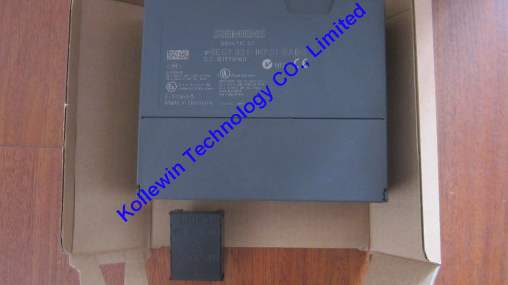
6ES7331-7KF02-0AB0 Siemens Analog input module

Introduction to 6ES7331-7KF02-0AB0

SIMATIC S7-300, ANALOG INPUT SM 331, OPTICALLY ISOLATED, 8AI, RESOLUTION 9/12/14 BITS, U/I/THERMOCOUPLE/RESISTANCE INTERRUPT, DIAGNOSTICS; 1X20PIN REMOVE/INSERT W. BACKPLANE BUS
 

Properties of 6ES7331-7KF02-0AB0

● 8 inputs in 4 channel groups

● Programmable measurement type at each channel group

– Voltage

– Current

– Resistance

– Temperature

● Programmable resolution at each channel group (9/12/14 bits + sign)

● Any measuring range selection per channel group

● Programmable diagnostics and diagnostic interrupt

● Programmable limit value monitoring for 2 channels

● Programmable hardware interrupt when limit is exceeded

● Electrically isolated to CPU and load voltage (not for 2-wire transducers)

Resolution

The measured value resolution is directly proportional to the selected integration time, that is, the measured value resolution increases in proportion to length of the integration time at the analog input channel.

Diagnostics

For information on diagnostics messages at the "group diagnostics" parameter, refer to chapter Diagnostic messages of analog input modules.

Hardware interrupts

Hardware interrupts for channel groups 0 and 1 can be programmed in STEP 7.

However,set a hardware interrupt only for the first channel of a channel group, that is, either at channel 0, or at channel 2.

Terminal assignment

The diagrams below show various wiring options The input impedance depends on the

setting of the measuring range module, see table Measurement types and ranges.


Wiring: Voltage measurement

4


Measuring range module settings of 6ES7331-7KF02-0AB0

 Measuring range    Measuring range module setting  
 ± 80 mV    A  
 ± 250 mV    
 ± 500 mV    
 ± 1,000 mV    
 ± 2.5 V    B  
 ± 5 V    
 1 V to 5 V    
 ± 10 V    


Wiring: 2-wire and 4-wire transducers for current measurement

5


Note
The interconnection between MANA and M- (terminals 11, 13, 15, 17, 19) is not required when
using grounded 4-wire transducers with non-isolated supply.


Measuring range module settings of 6ES7331-7KF02-0AB0

 Measuring range      Measuring range module setting  
 2-wire transducer    4 mA to 20 mA    D  
 4-wire transducer    ± 3.2 mA    C  
   ± 10 mA    
   0 mA to 20 mA    
   4 mA to 20 mA    
   ± 20 mA    


CAUTION
Measuring range module in "Current" position
Any voltage measurement will destroy the measuring range module if "current" measuring mode is set. 

Wiring: 2-, 3- and 4-wire connection of resistance transducers or thermoresistors

6


Measuring range module settings

 Measuring range      Measuring range module setting  
 150 Ω      A  
 300 Ω      
 600 Ω      
 Thermoresistor (linear, 4-wire connection)   Pt 100 Klima  A  
(temperature measurement) RTD-4L  Ni 100 Klima  
  Pt 100 Standard  
  Ni 100 Standard  


Note
• "Resistance measurement" is only available at one channel per group. The "2nd" channel of the group is used accordingly for current measuring mode (IC). The "1st" channel of the group returns the measured value. The "2nd" channel of the group is assigned the default overflow value "7FFFH."
• There is no compensation for power resistors for "2- and 3-wire connections". 


Wiring: Thermocouples with external compensation
Insert a bridge between Comp+ and MANA when using the internal compensation.

7


Measuring range module settings

 Measuring range      Measuring range module setting  
Thermocouple TC-I Type N [NiCrSi-NiSi]  A  
(internal comparison) (thermal Type E [NiCr-CuNi]  
voltage measurement) Type J [Fe-CuNi]  
Linearization is ignored Type K [NiCr-Ni]  
Thermocouple TC-E Type L [Fe-CuNi]  
(external comparison)    
(thermovoltage measurement)    
Linearization is ignored    
Thermocouple Type N [NiCrSi-NiSi]  A  
(linear, internal comparison) Type E [NiCr-CuNi]  
(temperature measurement) TCIL Type J [Fe-CuNi]  
Thermocouple Type K [NiCr-Ni]  
(linear, external comparison) Type L [Fe-CuNi]  
(temperature measurement) TCEL    


Note
• An interconnection of M- and MANA is prohibited when using grounded thermocouples. In
this case, you must ensure that low-resistance equipotential bonding is in place so that
the permitted common-mode voltage is not exceeded.
• Interconnect M- and MANA when using non-grounded thermocouples 


Technical specifications of Analog input module 6ES7331-7KF02-0AB0

      1
SIMATIC S7-300, ANALOG INPUT SM 331, OPTICALLY ISOLATED, 8AI, RESOLUTION 9/12/14 BITS, U/I/THERMOCOUPLE/RESISTANCE INTERRUPT, DIAGNOSTICS; 1X20PIN REMOVE/INSERT W. BACKPLANE BUS
 
Supply voltage
Load voltage L+
Rated value (DC) 24 V
Reverse polarity protection Yes
Input current
from load voltage L+ (without load), max. 200 mA
from backplane bus 5 V DC, max. 50 mA
Power losses
Power loss, typ. 1 W
Analog inputs
Number of analog inputs 8
Number of analog inputs for resistance measurement 4
permissible input voltage for voltage input (destruction limit), max. 20 V; continuous; 75 V for max. 1 s (mark to space ratio 1:20)
permissible input current for current input (destruction limit), max. 40 mA
Input ranges
Voltage Yes
Current Yes
Thermocouple Yes
Resistance thermometer Yes
Resistance Yes
Input ranges (rated values), voltages
0 to +10 V No
1 to 5 V Yes
Input resistance (1 to 5 V) 100 kΩ
1 to 10 V No
-1 V to +1 V Yes
Input resistance (-1 V to +1 V) 10 MΩ
-10 V to +10 V Yes
Input resistance (-10 V to +10 V) 100 kΩ
-2.5 V to +2.5 V Yes
Input resistance (-2.5 V to +2.5 V) 100 kΩ
-250 mV to +250 mV Yes
Input resistance (-250 mV to +250 mV) 10 MΩ
-5 V to +5 V Yes
Input resistance (-5 V to +5 V) 100 kΩ
-50 mV to +50 mV No
-500 mV to +500 mV Yes
Input resistance (-500 mV to +500 mV) 10 MΩ
-80 mV to +80 mV Yes
Input resistance (-80 mV to +80 mV) 10 MΩ
Input ranges (rated values), currents
0 to 20 mA Yes
Input resistance (0 to 20 mA) 25 Ω
-10 to +10 mA Yes
Input resistance (-10 to +10 mA) 25 Ω
-20 to +20 mA Yes
Input resistance (-20 to +20 mA) 25 Ω
-3.2 to +3.2 mA Yes
Input resistance (-3.2 to +3.2 mA) 25 Ω
4 to 20 mA Yes
Input resistance (4 to 20 mA) 25 Ω
Input ranges (rated values), thermoelements
Type B No
Type E Yes
Input resistance (Type E) 10 MΩ
Type J Yes
Input resistance (type J) 10 MΩ
Type K Yes
Input resistance (Type K) 10 MΩ
Type L Yes
Input resistance (Type L) 10 MΩ
Type N Yes
Input resistance (Type N) 10 MΩ
Type R No
Type S No
Type T No
Type U No
Type TXK/TXK(L) to GOST No
Input ranges (rated values), resistance thermometers
Cu 10 No
Ni 100 Yes; Standard
Input resistance (Ni 100) 10 MΩ
Ni 1000 No
LG-Ni 1000 No
Ni 120 No
Ni 200 No
Ni 500 No
Pt 100 Yes; Standard
Input resistance (Pt 100) 10 MΩ
Pt 1000 No
Pt 200 No
Pt 500 No
Input ranges (rated values), resistors
0 to 150 ohms Yes
Input resistance (0 to 150 ohms) 10 MΩ
0 to 300 ohms Yes
Input resistance (0 to 300 ohms) 10 MΩ
0 to 600 ohms Yes
Input resistance (0 to 600 ohms) 10 MΩ
0 to 6000 ohms No
Thermocouple (TC)
for thermocouples Type E, J, K, L, N
Temperature compensation
Parameterizable Yes
internal temperature compensation Yes
external temperature compensation with compensations socket Yes
Resistance thermometer (RTD)
Characteristic linearization
for resistance thermometer Pt100 (standard, climatic range), Ni100 (standard, climatic range)
Characteristic linearization
Parameterizable Yes
Cable length
Cable length, shielded, max. 200 m; 50 m at 80 mV and thermocouples
Analog value creation
Measurement principle integrating
Integrations and conversion time/ resolution per channel
Resolution with overrange (bit including sign), max. 15 bit; Unipolar: 9/12/12/14 bits; bipolar: 9 bits + sign/12 bits + sign/12 bits + sign/14 bits + sign
Integration time, parameterizable Yes; 2.5/ 16.67/ 20/ 100 ms
Basic conversion time, ms 3 / 17 / 22 /102 ms
Interference voltage suppression for interference frequency f1 in Hz 400 / 60 / 50 / 10 Hz
Encoder
Connection of signal encoders
for current measurement as 2-wire transducer Yes
for current measurement as 4-wire transducer Yes
for resistance measurement with 2-conductor connection Yes
for resistance measurement with 3-conductor connection Yes
for resistance measurement with 4-conductor connection Yes
Errors/accuracies
Operational limit in overall temperature range
Voltage, relative to input area +/- 1 %; +/-1% (80 mV); +/-0.6% (250 to 1000 mV); +/-0.8% (2.5 to 10 V)
Current, relative to input area +/- 0,7 %; From 3.2 to 20 mA
Impedance, relative to input area +/- 0,7 %; 150, 300, 600 Ohm
Resistance-type thermometer, relative to input area +/- 0,7 %; +/-0.7% (Pt100/ Ni100); +/-0.8% (Pt100 climate)
Basic error limit (operational limit at 25 °C)
Voltage, relative to input area +/- 0,6 %; +/-0.4% (250 to 1000 mV); +/-0.6 % (2.5 to 10 mV); +/-0.7 % (80 mV)
Current, relative to input area +/- 0,5 %; 3.2 to 20 mA
Impedance, relative to input area +/- 0,5 %; 150, 300, 600 Ohm
Resistance-type thermometer, relative to input area +/- 0,6 %; +/-0.5% (Pt100/ Ni100); +/-0.6% (Pt100 climate)
Isochronous mode
Isochronous operation (application synchronized up to terminal) No
Interrupts/diagnostics/status information
Alarms
Diagnostic alarm Yes; Parameterizable, channels 0 and 2
Limit value alarm Yes; Parameterizable
Diagnostic messages
Diagnostic functions Yes; Parameterizable
Diagnostic information readable Yes
Diagnostics Yes
Diagnostics indication LED
Group error SF (red) Yes
Galvanic isolation
Galvanic isolation analog inputs
between the channels No
between the channels and the backplane bus Yes
Isolation
Isolation checked with 500 V DC
Connection method
required front connector 20-pin
Dimensions
Width 40 mm
Height 125 mm
Depth 120 mm
Weight
Weight, approx. 250 g


Measurement types and ranges
Introduction
Module SM 331; AI 8 x 12 Bit has measuring range modules
The measurement type and range is configured at the "measuring range" parameter in STEP 7.
The default setting of the module is "voltage" measurement with "± 10V" range. You can use these default settings without having to program the SM 331; AI 8 x 12 Bit in STEP 7.
Measuring range modules
You may have to change the position of the measuring range modules to suit the measurement type and range (see the chapter Setting the measuring types and ranges of analog input channels ).

The necessary settings are also available on the module's imprint. Mark the position of the measuring range module on the front door.


Additional information on SM 331; AI 8 x 12 Bit
Unused channels
As certain programmed inputs may remain unused due to the channel group configuration,make allowances for the special features of these inputs outlined below in order to be able to use the diagnostics functions at these used channels:
● Voltage measurement (except 1 V to 5V) and for thermocouples: Short-circuit unused channels and connect these with MANA. This optimizes interference immunity of the analog input module. Set the "disabled" value at the "measurement type" parameter for unused channels. This setting reduces module cycle times. Also short-circuit the COMP input if this is not used.
● Measuring range 1 V to 5 V: wire the used and unused inputs of the same channel group in parallel.
● Current measurement, 2-wire transducer: There are two options of wiring the channel circuit.
a) Open unused input; channel group diagnostics disabled. If you were to enable diagnostics, the analog module would trigger a single diagnostic interrupt, and light up its SF LED.
b) Loading the unused input using a 1.5 kΩ to 3.3 kΩ resistor. This allows you to enable diagnostics for this channel group.
● Current measurement 4 mA to 20 mA, 4-wire transducer: wire the unused inputs of the same channel group in series.

All channels deactivated
If you disable all input channels of the module and enable diagnostics at the parameters of SM 331; AI 8 x 12 Bit, the module does not report "external auxiliary voltage missing."

Line continuity check for the 4 mA to 20 mA measuring range
If you configured a measuring range of 4 mA to 20 mA, and enabled the line continuity check, the analog input module logs a wire-break event to diagnostics data when the current drops below 3.6 mA.
The module also triggers a diagnostics interrupt if this function is enabled in the program.A wire break can only be signaled by means of the lit SF LED and the diagnostic bytes must be evaluated in the user program if diagnostics interrupts are disabled.
If you configured a measuring range of 4 mA to 20 mA, disabled the line continuity check,and enabled diagnostic interrupts, the module triggers a diagnostic interrupt when the underflow value is reached.

Line continuity check
The line continuity check is designed only for temperature measurements (thermocouples and thermoresistors.)


USER'S manual PDF of 331-7KF02, please refer from Page 370- Page 385:

S7-300 Modules data & USER'S MANUAL


Our company (Kollewin Technology CO., Limited) have a new product,

named 6ES7331-7KF02-0AB0,

it is 100% compatible with Siemens original part.

Part#: 6ES7331-7KF02-0AB0


Unit price:USD367.00/pc  buy buttom
Description: S7-300 Analog input module
Manufacturer: Kollewin
Approx. Weight: 0.3 Kg
Warranty: 1 year
Origin: China


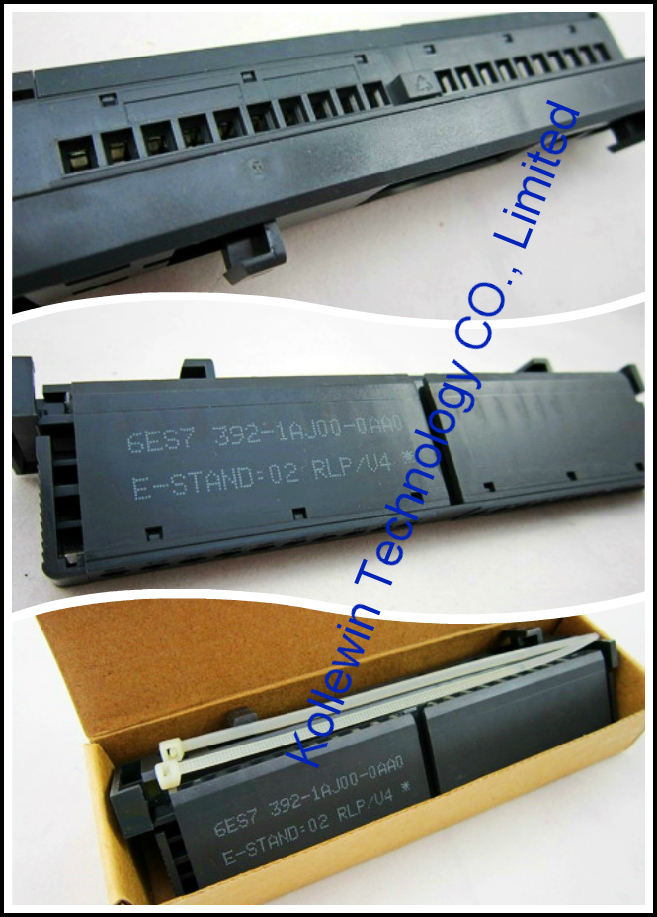
Here, you need 1 piece of 20pin front connector to connect with 6ES7331-7KF02-0AB0.

Our compatible 6ES7 392-1AJ00-0AA0 can meet your requirements.


6ES7 392-1AJ00-0AA0  @USD10.50/pc   buy buttom


Technical data sheet of our SM 331  6ES7331-7KF02-0AB0

Model

SM331

8AI

Product  Description

8AI;

Full-function temperature measurement modules; Resolution:16bits;

Short-circuit protection ;High immunity;stable

Power consumption

·Rate value

24V DC

·From backplane bus current consumption

100mA

·From L+

25mA

·Power loss

1W

The power of transmitter


·Supply current

Per channel (Max):60mA

·short-circuit protection

Yes

Number of analog inputs

8

Cable Length (Shielded)

200m

Max.For 80mV:50m

Input type and input range


·voltage

±80mV, ±250mV,

±500mV,±1V, ±2.5V ±5V,1~5V, ±10V

·current(4wire)

±3.2mA, ±10mA, ±20mA, 4~20mA

·current(2wire)

4~20mA

·tesistance

600Ω, 300Ω, 150Ω,

·thermocouple

K,J,N,E,L

·RTD

Pt100,Ni100

A/D resolution

16bits

Basic conversion time(per channel)

0.5ms/12.5ms/25ms/50ms

Interference frequency suppression

400/60/50/10Hz

Tolerance(Over entire temperature range)

·Voltage

±0.6%

·Current

±0.6%

·resistance

±0.6%

·temperature

±1℃

Interrupts

Diagnostic interrupt

Per group Yes,Configurable

Limit-value interrupt

Yes,Configurable

Isolation tested for contact

·Between channels

None

·Between channels and backplane bu

Yes

Front connector

20-pin

Dimensions(W x H x D)(mm)

40×125×120

Order Number

 331-7KF02-0AB0


Picture of 6ES7331-7KF02-0AB0

331-7KF02-0AB0

More compatible Siemens S7-200/300 modules we can offer:

Model Product Description
SM7-200 DIGITAL MODULE
  6ES7221-1BH22-0XA0 EM221 16 DI 24V DC
  6ES7221-1BL22-0XA0 EM221 32 DI 24V DC
  6ES7222-1BF22-0XA0 EM222 8DO,DC 24V
  6ES7222-1HF22-0XA0   EM222 8DO,relay
  6ES7222-1BH22-0XA0 EM222 16 DO 24V DC
  6ES7222-1HH22-0XA0 EM222 16 DO RELAY
  6ES7222-1BL22-0XA0 EM222 32 DO 24V DC
  6ES7223-1HF22-0XA0 EM223 4DI/4DO,DC 24V relay
  6ES7223-1BH22-0XA0 EM223 8 DI/ 8 DO 24V DC
  6ES7223-1PH22-0XA0 EM223 8 DI 24V DC/8 DO RELAY
  6ES7223-1BL22-0XA0 EM223 16 DI/ 16 DO 24V DC
  6ES7223-1PL22-0XA0 EM223 16 DI 24V DC/ 16 DO RELAY
  6ES7223-1BF22-0XA0 4 DI/4DO,24 VDC
  6ES7221-1BF22-0XA0 8 DI,24V DC
SM7-200 ANALOG MODULE
  6ES7231-0HC22-0XA0 EM231 4 AI x 12 Bits
  6ES7231-0HF22-0XA0 EM231 8 AI x 12/11 BIT 
  6ES7231-7PC22-0XA0 EM231 4 RTD
  6ES7231-7PD22-0XA0 EM231 4 TC
  6ES7231-7PH22-0XA0 EM231 8 TC
  6ES7231-7PL22-0XA0 16AI, T/C INPUT MOD, 16BIT
  6ES7231-7PB22-0XA0 2AI, RTD INPUT MOD. 16BIT 
  6ES7232-0HB22-0XA0 EM232 2 AO x 12 Bits
  6ES7232-0HD22-0XA0 EM232 4 AO x 12 Bits
  6ES7235-0KD22-0XA0 EM235 4 AI/ 1 AO x 12 Bits
SM7-300 DIGITAL MODULE
  6ES7321-1BH02-0AA0 SM321 16 DI 24 VDC
  6ES7321-1FH00-0AA0 SM321 16 DI  AC 230V
  6ES7321-1BL00-0AA0 SM321 32 DI 24 VDC
  6ES7322-1BF01-0AA0 SM322,8DO,24VDC,2A
  6ES7322-1BH01-0AA0 SM322 16 DO 24 VDC/ 0.5A
  6ES7322-1HH01-0AA0 SM322 16 DO RELAY
  6ES7322-1BL00-0AA0 SM322 32 DO 24V DC/0.5A
  6ES7323-1BL00-0AA0 SM323 16DI 24V DC/ 16DO 24V DC 0.5A
SM7-300 ANALOG MODULE
  6ES7331-1KF01-0AB0 SM331 8 AI x 13 Bits
  6ES7331-7KF02-0AB0 SM331 8 AI X 14 Bits
  6ES7331-7PF01-0AB0 SM331 8 AI,RTD
  6ES7331-7PF11-0AB0 SM331 8 AI,TC
  6ES7332-5HD01-0AB0 SM332 4 AO x 12 Bits
  6ES7332-5HF00-0AB0 SM 332 8 AO x 12 BITS
SIMATIC DP  IM 153 
  6ES7153-1AA03-0XB0 SIMATIC DP, INTERFACE

IM 153-1, FOR ET 200M,

FOR MAX. 8 S7-300 MODULES
  6ES7365-0BA01-0AA0 IM 365 Rack expansion module,be deployed with a central controller and a expansion rack


More pictures for your reference:

S7-300 322-1BH02 322-1BL00 S7-200 321-1BL00 331-1KF01 product 3311kf01 3311kf01-00


Please feel free to contact me for any question!

Contact person: Miss Nancy

Skype: kollewin
E-mail: nancy@kollewin.com
Tel: +86-0755-26898905-8006
Website: www.kollewin.com


Jul 4 2013

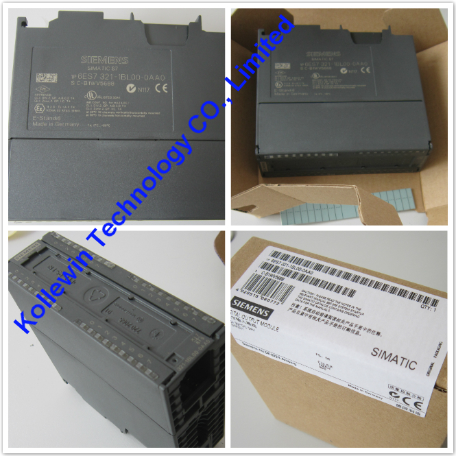
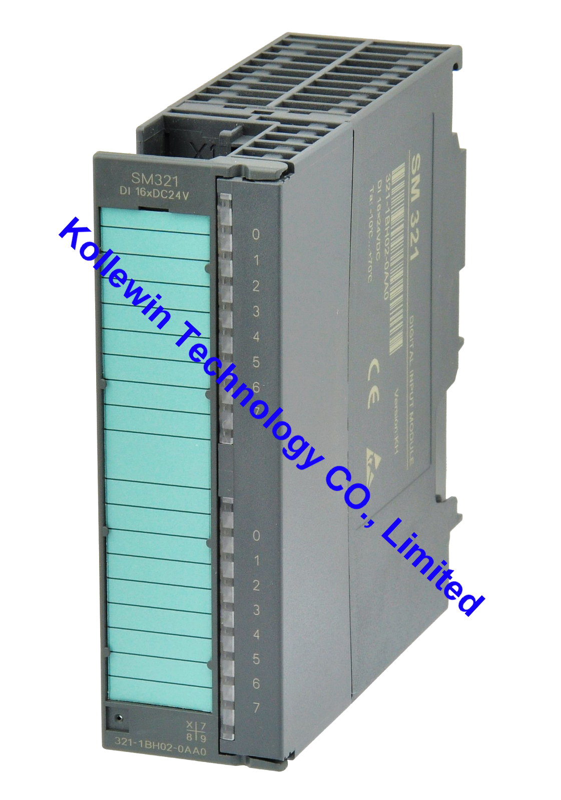
6ES7321-1BH02-0AA0 Siemens Digital input module

Introduction to 6ES7321-1BH02-0AA0

SIMATIC S7-300, DIGITAL INPUT SM 321, OPTICALLY ISOLATED, 16DI, 24 V DC, 1 X 20 PIN

Order number: "SIPLUS S7-300 module"
6AG1321-1BH02-2AA0
Properties
Properties of SM 321; DI 16 x DC 24 V:
● 16 inputs, electrically isolated in groups of 16
● Rated input voltage 24 VDC
● suitable for switches and 2- /3-/4-wire proximity switches (BEROs)


Wiring and block diagrams of SM 321; DI 16 x DC 24 V

14


Technical specifications of 6ES7321-1BH02-0AA0

        5
 
SIMATIC S7-300, DIGITAL INPUT SM 321, OPTICALLY ISOLATED, 16DI, 24 V DC, 1 X 20 PIN
 
Supply voltage
Load voltage L+
Rated value (DC) 24 V
permissible range, lower limit (DC) 20.4 V
permissible range, upper limit (DC) 28.8 V
Input current
from backplane bus 5 V DC, max. 10 mA
Power losses
Power loss, typ. 3.5 W
Digital inputs
Number/binary inputs 16
Input characteristic curve acc. to IEC 61131, Type 1 Yes
Number of simultaneously controllable inputs
horizontal installation
up to 40 °C, max. 16
up to 60 °C, max. 16
vertical installation
up to 40 °C, max. 16
Input voltage
Type of input voltage DC
Rated value, DC 24 V
for signal "0" -30 to +5 V
for signal "1" 13 to 30 V
Input current
for signal "1", typ. 7 mA
Input delay (for rated value of input voltage)
for standard inputs
Parameterizable No
at "0" to "1", min. 1.2 ms
at "0" to "1", max. 4.8 ms
Cable length
Cable length, shielded, max. 1000 m
Cable length unshielded, max. 600 m
Encoder
Connectable encoders
2-wire sensor Yes
Permissible quiescent current (2-wire sensor), max. 1.5 mA
Isochronous mode
Isochronous operation (application synchronized up to terminal) No
Interrupts/diagnostics/status information
Alarms
Alarms No
Diagnostic alarm No
Hardware interrupt No
Diagnostic messages
Diagnostic functions No
Diagnostics indication LED
Status indicator digital input (green) Yes
Galvanic isolation
Galvanic isolation digital inputs
between the channels No
between the channels, in groups of 16
between the channels and the backplane bus Yes; Optocoupler
Permissible potential difference
between different circuits 75 VDC / 60 VAC
Isolation
Isolation checked with 500 V DC
Connection method
required front connector 20-pin
Dimensions
Width 40 mm
Height 125 mm
Depth 120 mm
Weight
Weight, approx. 200 g


USER'S manual PDF of 321-1BH02, please refer from Page 79- Page 82:


S7-300 Modules data & USER'S MANUAL


Our company (Kollewin Technology CO., Limited) have a new product,

named 6ES7321-1BH02-0AA0,

it is 100% compatible with Siemens original part.


Part#: 6ES7321-1BH02-0AA0


Unit price:USD95.00/pc  buy buttom
Description: S7-300
Digital input module
Manufacturer: Kollewin
Approx. Weight: 0.3 Kg
Warranty: 1 year
Origin: China


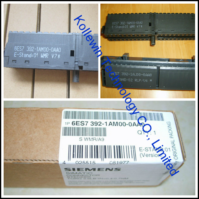
Here, you need 1 piece of 40pin front connector to connect with 6ES7321-1BH02-0AA0.

Our compatible 6ES7 392-1AM00-0AA0 can meet your requirements.

6ES7 392-1AM00-0AA0  @USD16.90/pc   buy buttom


Technical data sheet of our SM 321  6ES7321-1BH02-0AA0

Model

SM321

Number of digital inputs:32

Product  Description

32DI 24V DC,
High immunity


Power consumption

·From bus current consumption

50mA

·Power loss

6.5W

Number of digital inputs

32

Cable Length (Shielded)

1,000m

Cable Length (unshielded)

600m

Input voltage

·Rate value

24V DC

·For ”0” signal

-30~5V DC

·For ”1” signal

13~30V DC

·Frequency range

/

Input current

7mA

Input delay


·From “0”  to “1”,Min

1.2~4.8ms

·From “1”  to “0”,Min

1.2~4.8ms

Front connector

40-pin

Input type

NPN

Connection of 2-wire BERO sensor

Yes

Permissible quiescent current

1.5mA

Isolation tested for contact

·Between channel and backplane bus

Yes

·Per group between channels

Yes

The status indicates

Green LED each channel

Dimensions(WxHx D)(mm)

40×125×120

Order Number

 321-1BL00-0AA0


Pictures of 6ES7321-1BH02-0AA0

321-1BH02-0AA0

322-1BH02


More compatible Siemens S7-200/300 modules we can offer:

Model Product Description
SM7-200 DIGITAL MODULE
  6ES7221-1BH22-0XA0 EM221 16 DI 24V DC
  6ES7221-1BL22-0XA0 EM221 32 DI 24V DC
  6ES7222-1BF22-0XA0 EM222 8DO,DC 24V
  6ES7222-1HF22-0XA0   EM222 8DO,relay
  6ES7222-1BH22-0XA0 EM222 16 DO 24V DC
  6ES7222-1HH22-0XA0 EM222 16 DO RELAY
  6ES7222-1BL22-0XA0 EM222 32 DO 24V DC
  6ES7223-1HF22-0XA0 EM223 4DI/4DO,DC 24V relay
  6ES7223-1BH22-0XA0 EM223 8 DI/ 8 DO 24V DC
  6ES7223-1PH22-0XA0 EM223 8 DI 24V DC/8 DO RELAY
  6ES7223-1BL22-0XA0 EM223 16 DI/ 16 DO 24V DC
  6ES7223-1PL22-0XA0 EM223 16 DI 24V DC/ 16 DO RELAY
  6ES7223-1BF22-0XA0 4 DI/4DO,24 VDC
  6ES7221-1BF22-0XA0 8 DI,24V DC
SM7-200 ANALOG MODULE
  6ES7231-0HC22-0XA0 EM231 4 AI x 12 Bits
  6ES7231-0HF22-0XA0 EM231 8 AI x 12/11 BIT 
  6ES7231-7PC22-0XA0 EM231 4 RTD
  6ES7231-7PD22-0XA0 EM231 4 TC
  6ES7231-7PH22-0XA0 EM231 8 TC
  6ES7231-7PL22-0XA0 16AI, T/C INPUT MOD, 16BIT
  6ES7231-7PB22-0XA0 2AI, RTD INPUT MOD. 16BIT 
  6ES7232-0HB22-0XA0 EM232 2 AO x 12 Bits
  6ES7232-0HD22-0XA0 EM232 4 AO x 12 Bits
  6ES7235-0KD22-0XA0 EM235 4 AI/ 1 AO x 12 Bits
SM7-300 DIGITAL MODULE
  6ES7321-1BH02-0AA0 SM321 16 DI 24 VDC
  6ES7321-1FH00-0AA0 SM321 16 DI  AC 230V
  6ES7321-1BL00-0AA0 SM321 32 DI 24 VDC
  6ES7322-1BF01-0AA0 SM322,8DO,24VDC,2A
  6ES7322-1BH01-0AA0 SM322 16 DO 24 VDC/ 0.5A
  6ES7322-1HH01-0AA0 SM322 16 DO RELAY
  6ES7322-1BL00-0AA0 SM322 32 DO 24V DC/0.5A
  6ES7323-1BL00-0AA0 SM323 16DI 24V DC/ 16DO 24V DC 0.5A
SM7-300 ANALOG MODULE
  6ES7331-1KF01-0AB0 SM331 8 AI x 13 Bits
  6ES7331-7KF02-0AB0 SM331 8 AI X 14 Bits
  6ES7331-7PF01-0AB0 SM331 8 AI,RTD
  6ES7331-7PF11-0AB0 SM331 8 AI,TC
  6ES7332-5HD01-0AB0 SM332 4 AO x 12 Bits
  6ES7332-5HF00-0AB0 SM 332 8 AO x 12 BITS
SIMATIC DP  IM 153 
  6ES7153-1AA03-0XB0 SIMATIC DP, INTERFACE

IM 153-1, FOR ET 200M,

FOR MAX. 8 S7-300 MODULES
  6ES7365-0BA01-0AA0 IM 365 Rack expansion module,be deployed with a central controller and a expansion rack


More pictures for your reference:

6ES7322-1BL00 3211bl00 321-1BL00 332-5HD01-0AB0 S7-300 322-1BL00 S7-200 331-1KF01 product 321-1BL00 3311kf01 3311kf01-00


Please feel free to contact me for any question!

Contact person: Miss Nancy

Skype: kollewin
E-mail: nancy@kollewin.com
Tel: +86-0755-26898905-8006
Website: www.kollewin.com
Jul 3 2013

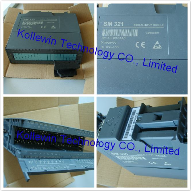
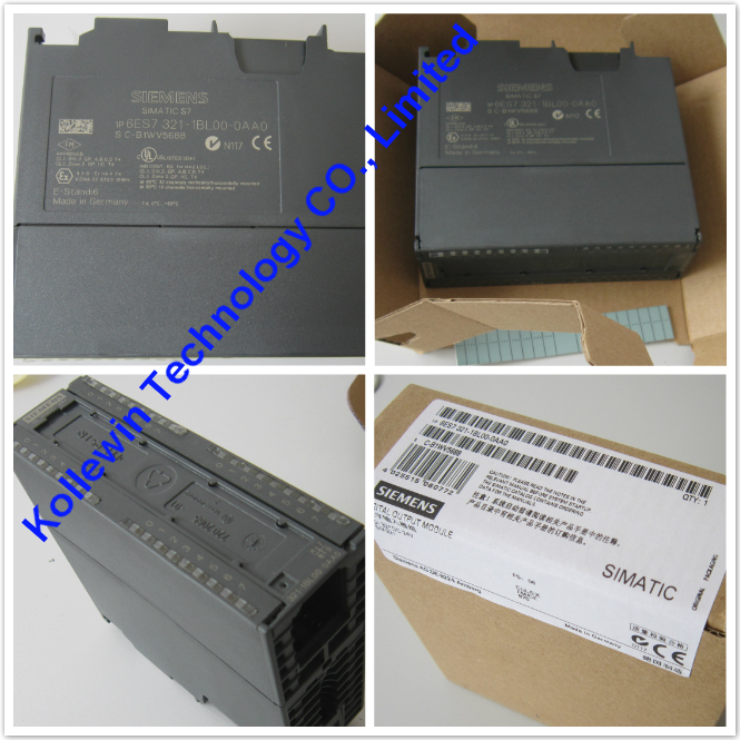
6ES7321-1BL00-0AA0 Siemens Digital input module

Introduction to 6ES7321-1BL00-0AA0

SIMATIC S7-300, DIGITAL INPUT SM 321, OPTICALLY ISOLATED 32DI, 24 V DC, 1 X 40 PIN

Order number: "Standard module"
6ES7321-1BL00-0AA0
Order number: "SIPLUS S7-300 module"
6AG1321-1BL00-2AA0
Properties
Properties of SM 321; DI 32 x DC 24 V:
● 32 inputs, isolated in groups of 16
● Rated input voltage 24 VDC
● Suitable for switches and 2-/3-/4-wire proximity switches (BEROs)


Wiring and block diagrams of SM 321; DI 32 x DC 24 V

11


Terminal assignment of SM 321; DI 32 x DC 24 V
The figure below shows how channels are assigned to addresses (input byte x up to input byte x+3).

12


Technical specifications of SM 321; DI 32 x DC 24 V

        3
 
SIMATIC S7-300, DIGITAL INPUT SM 321, OPTICALLY ISOLATED 32DI, 24 V DC, 1 X 40 PIN
 
Supply voltage
Load voltage L+
Rated value (DC) 24 V
permissible range, lower limit (DC) 20.4 V
permissible range, upper limit (DC) 28.8 V
Input current
from backplane bus 5 V DC, max. 15 mA
Power losses
Power loss, typ. 6.5 W
Digital inputs
Number/binary inputs 32
Input characteristic curve acc. to IEC 61131, Type 1 Yes
Number of simultaneously controllable inputs
horizontal installation
up to 40 °C, max. 32
up to 60 °C, max. 16
vertical installation
up to 40 °C, max. 32
Input voltage
Type of input voltage DC
Rated value, DC 24 V
for signal "0" -30 to +5 V
for signal "1" 13 to 30 V
Input current
for signal "1", typ. 7 mA
Input delay (for rated value of input voltage)
for standard inputs
Parameterizable No
at "0" to "1", min. 1.2 ms
at "0" to "1", max. 4.8 ms
Cable length
Cable length, shielded, max. 1000 m
Cable length unshielded, max. 600 m
Encoder
Connectable encoders
2-wire sensor Yes
Permissible quiescent current (2-wire sensor), max. 1.5 mA
Isochronous mode
Isochronous operation (application synchronized up to terminal) No
Interrupts/diagnostics/status information
Alarms
Alarms No
Diagnostic alarm No
Hardware interrupt No
Diagnostic messages
Diagnostic functions No
Diagnostics indication LED
Status indicator digital input (green) Yes
Galvanic isolation
Galvanic isolation digital inputs
between the channels No
between the channels, in groups of 16
between the channels and the backplane bus Yes; Optocoupler
Permissible potential difference
between different circuits 75 VDC / 60 VAC
Isolation
Isolation checked with 500 V DC
Connection method
required front connector 40-pin
Dimensions
Width 40 mm
Height 125 mm
Depth 120 mm
Weight
Weight, approx. 260 g


USER'S manual PDF of 321-1BL00, please refer to Page 72- Page 75:

S7-300 Modules data & USER'S MANUAL


Our company (Kollewin Technology CO., Limited) have a new product,

named 6ES7321-1BL00-0AA0,

it is 100% compatible with Siemens original part.


Part#: 6ES7321-1BL00-0AA0

Unit price:USD191.00/pc  buy buttom
Description: S7-300 Digital input module
Manufacturer: Kollewin
Approx. Weight: 0.3 Kg
Warranty: 1 year
Origin: China


Here, you also need 1 piece of 40 pin front connector to connect with it..

Our compatible 6ES7 392-1AM00-0AA0 can meet your requirements.


6ES7 392-1AM00-0AA0  @USD16.90/pc   buy buttom


Technical data sheet of our SM 321  6ES7321-1BL00-0AA0

Model

SM321

Number of digital inputs:32

Product  Description

32DI 24V DC,
High immunity


Power consumption

·From bus current consumption

50mA

·Power loss

6.5W

Number of digital inputs

32

Cable Length (Shielded)

1,000m

Cable Length (unshielded)

600m

Input voltage

·Rate value

24V DC

·For ”0” signal

-30~5V DC

·For ”1” signal

13~30V DC

·Frequency range

/

Input current

7mA

Input delay


·From “0”  to “1”,Min

1.2~4.8ms

·From “1”  to “0”,Min

1.2~4.8ms

Front connector

40-pin

Input type

NPN

Connection of 2-wire BERO sensor

Yes

Permissible quiescent current

1.5mA

Isolation tested for contact

·Between channel and backplane bus

Yes

·Per group between channels

Yes

The status indicates

Green LED each channel

Dimensions(WxHx D)(mm)

40×125×120

Order Number

 321-1BL00-0AA0


Pictures of 6ES7321-1BL00-0AA0

321-1BL00

3211bl00

More compatible Siemens S7-200/300 modules we can offer:

Model Product Description
SM7-200 DIGITAL MODULE
  6ES7221-1BH22-0XA0 EM221 16 DI 24V DC
  6ES7221-1BL22-0XA0 EM221 32 DI 24V DC
  6ES7222-1BF22-0XA0 EM222 8DO,DC 24V
  6ES7222-1HF22-0XA0   EM222 8DO,relay
  6ES7222-1BH22-0XA0 EM222 16 DO 24V DC
  6ES7222-1HH22-0XA0 EM222 16 DO RELAY
  6ES7222-1BL22-0XA0 EM222 32 DO 24V DC
  6ES7223-1HF22-0XA0 EM223 4DI/4DO,DC 24V relay
  6ES7223-1BH22-0XA0 EM223 8 DI/ 8 DO 24V DC
  6ES7223-1PH22-0XA0 EM223 8 DI 24V DC/8 DO RELAY
  6ES7223-1BL22-0XA0 EM223 16 DI/ 16 DO 24V DC
  6ES7223-1PL22-0XA0 EM223 16 DI 24V DC/ 16 DO RELAY
  6ES7223-1BF22-0XA0 4 DI/4DO,24 VDC
  6ES7221-1BF22-0XA0 8 DI,24V DC
SM7-200 ANALOG MODULE
  6ES7231-0HC22-0XA0 EM231 4 AI x 12 Bits
  6ES7231-0HF22-0XA0 EM231 8 AI x 12/11 BIT 
  6ES7231-7PC22-0XA0 EM231 4 RTD
  6ES7231-7PD22-0XA0 EM231 4 TC
  6ES7231-7PH22-0XA0 EM231 8 TC
  6ES7231-7PL22-0XA0 16AI, T/C INPUT MOD, 16BIT
  6ES7231-7PB22-0XA0 2AI, RTD INPUT MOD. 16BIT 
  6ES7232-0HB22-0XA0 EM232 2 AO x 12 Bits
  6ES7232-0HD22-0XA0 EM232 4 AO x 12 Bits
  6ES7235-0KD22-0XA0 EM235 4 AI/ 1 AO x 12 Bits
SM7-300 DIGITAL MODULE
  6ES7321-1BH02-0AA0 SM321 16 DI 24 VDC
  6ES7321-1FH00-0AA0 SM321 16 DI  AC 230V
  6ES7321-1BL00-0AA0 SM321 32 DI 24 VDC
  6ES7322-1BF01-0AA0 SM322,8DO,24VDC,2A
  6ES7322-1BH01-0AA0 SM322 16 DO 24 VDC/ 0.5A
  6ES7322-1HH01-0AA0 SM322 16 DO RELAY
  6ES7322-1BL00-0AA0 SM322 32 DO 24V DC/0.5A
  6ES7323-1BL00-0AA0 SM323 16DI 24V DC/ 16DO 24V DC 0.5A
SM7-300 ANALOG MODULE
  6ES7331-1KF01-0AB0 SM331 8 AI x 13 Bits
  6ES7331-7KF02-0AB0 SM331 8 AI X 14 Bits
  6ES7331-7PF01-0AB0 SM331 8 AI,RTD
  6ES7331-7PF11-0AB0 SM331 8 AI,TC
  6ES7332-5HD01-0AB0 SM332 4 AO x 12 Bits
  6ES7332-5HF00-0AB0 SM 332 8 AO x 12 BITS
SIMATIC DP  IM 153 
  6ES7153-1AA03-0XB0 SIMATIC DP, INTERFACE

IM 153-1, FOR ET 200M,

FOR MAX. 8 S7-300 MODULES
  6ES7365-0BA01-0AA0 IM 365 Rack expansion module,be deployed with a central controller and a expansion rack


More pictures for your reference:

332-5HD01-0AB0 331-7KF02-0AB0 S7-300 322-1BH02 322-1BL00 S7-200 331-1KF01 product 3311kf01 3311kf01-00


Please feel free to contact me for any question!

Contact person: Miss Nancy

Skype: kollewin
E-mail: nancy@kollewin.com
Tel: +86-0755-26898905-8006
Website: www.kollewin.com
Jul 2 2013

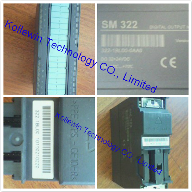
6ES7322-1BL00-0AA0 Siemens Digital output module

Introduction to 6ES7322-1BL00-0AA0

SIMATIC S7-300, DIGITAL OUTPUT SM 322, OPTICALLY ISOLATED, 32DO, 24V DC, 0.5A, 1 X 40 PIN, SUM OF OUTPUT CURRENTS 4A/GROUP (16A/MODULE)


Properties of 6ES7322-1BL00-0AA0
● 32 outputs, electrically isolated in groups of 8
● Output current 0.5 A
● Rated load voltage 24 VDC
● Suitable for solenoid valves, DC contactors and signal lamps
Use of the module with high-speed counters

Please note when using the module in combination with high-speed counters:
Note
When using a mechanical contact to switch on the 24-V power supply to SM 322;
DO 32 x DC 24 V/0.5 A, its outputs will carry "1" signal for the duration of ca. 50 μs due to the circuit structure.


Wiring and block diagram of SM 322; DO 32 x DC 24 V/ 0.5 A

13


Terminal assignment of SM 322; DO 32 x DC 24 V/ 0.5 A
The figure below shows the channel addressing (output byte x to output byte x+3).

12


Technical specifications of SM 322; 6ES7322-1BL00-0AA0


    4
SIMATIC S7-300, DIGITAL OUTPUT SM 322, OPTICALLY ISOLATED, 32DO, 24V DC, 0.5A, 1 X 40 PIN, SUM OF OUTPUT CURRENTS 4A/GROUP (16A/MODULE)
 
Supply voltage
Load voltage L+
Rated value (DC) 24 V
permissible range, lower limit (DC) 20.4 V
permissible range, upper limit (DC) 28.8 V
Input current
from load voltage L+ (without load), max. 160 mA
from backplane bus 5 V DC, max. 110 mA
Power losses
Power loss, typ. 6.6 W
Digital outputs
Number/binary outputs 32
Limitation of inductive shutdown voltage to L+ (-53 V)
Lamp load, max. 5 W
Load resistance range
lower limit 48 Ω
upper limit 4 kΩ
Output voltage
for signal "1", min. L+ (-0.8 V)
Output current
for signal "1" rated value 0.5 A
for signal "1" permissible range for 0 to 40 °C, max. 0.6 A
for signal "1" minimum load current 5 mA
for signal "0" residual current, max. 0.5 mA
Switching frequency
with resistive load, max. 100 Hz
with inductive load, max. 0.5 Hz
on lamp load, max. 10 Hz
Aggregate current of outputs (per group)
horizontal installation
up to 40 °C, max. 4 A
up to 60 °C, max. 3 A
vertical installation
up to 40 °C, max. 2 A
Cable length
Cable length, shielded, max. 1000 m
Cable length unshielded, max. 600 m
Interrupts/diagnostics/status information
Alarms
Diagnostic alarm No
Diagnostic messages
Diagnostics No
Wire break No
Short circuit No
Missing load voltage No
Diagnostics indication LED
Rated load voltage PWR (green) No
Fuse OK FSG (green) No
Galvanic isolation
Galvanic isolation digital outputs
between the channels, in groups of 8
between the channels and the backplane bus Yes; Optocoupler
Isolation
Isolation checked with 500 V DC
Connection method
required front connector 40-pin
Dimensions
Width 40 mm
Height 125 mm
Depth 120 mm
Weight
Weight, approx. 260 g


USER'S manual PDF of 322-1BL00, please refer to Page 143- Page 146:

S7-300 Modules data & USER'S MANUAL


Our company (Kollewin Technology CO., Limited) have a new product,

named 6ES7322-1BL00-0AA0.

It is 100% compatible with Siemens original part.


Part#: 6ES7322-1BL00-0AA0

Unit price:USD264.00/pc  buy buttom
Manufacturer: Kollewin
Approx. Weight: 0.3 Kg
Warranty: 1 year
Origin: China


Here, you need 1 pc 40pin front connector to connect with it.

Our compatible 6ES7 392-1AM00-0AA0 can meet your requirements.

6ES7 392-1AM00-0AA0  @USD16.90/pc   buy buttom


Technical data sheet of our SM 322  6ES7322-1BL00-0AA0

Model

SM322

Number of digital outputs:32

Product  Description

32DO,24V DC; Transistor;

Optical isolation with high immunity

Power consumption

·From  bus current consumption

90mA

·Power loss

6W

Number of digital outputs

32

Cable Length (Shielded)

1,000m

Cable Length (unshielded)

600m

Short-circuit protection

Yes,Electronic

Inductive cutoff voltage

L+(-53V)

Lamp load Max

5W

Output voltage:”1” signal

Min,L+(-0.8V)

Output current:”1” signal

0.5A

Lifetime contact mechanical

/

Lifetime contact  mechanical  rated load voltage)

/

Sum of output currents(per group)

4A

IIsolation tested for contact

·To backplane bus

Yes,Optocoupler

·To per group between channels

Yes

Switching frequency for contacts

·Resistive loads,Max

100Hz

·Capacitive loads,Max

0.5Hz

·Lamp loads,Max

10Hz

·Mechanical load,Max

/

The status indicates

Green LED each channel

Front connector

40-pin

Dimensions(W x H x D)(mm)

40×125×120

Order Number

 322-1BL00-0AA0


Pictures of 6ES7322-1BL00-0AA0

322-1BL00 6ES7322-1BL00


More compatible Siemens S7-200/300 modules we can offer:

Model Product Description
SM7-200 DIGITAL MODULE
  6ES7221-1BH22-0XA0 EM221 16 DI 24V DC
  6ES7221-1BL22-0XA0 EM221 32 DI 24V DC
  6ES7222-1BF22-0XA0 EM222 8DO,DC 24V
  6ES7222-1HF22-0XA0   EM222 8DO,relay
  6ES7222-1BH22-0XA0 EM222 16 DO 24V DC
  6ES7222-1HH22-0XA0 EM222 16 DO RELAY
  6ES7222-1BL22-0XA0 EM222 32 DO 24V DC
  6ES7223-1HF22-0XA0 EM223 4DI/4DO,DC 24V relay
  6ES7223-1BH22-0XA0 EM223 8 DI/ 8 DO 24V DC
  6ES7223-1PH22-0XA0 EM223 8 DI 24V DC/8 DO RELAY
  6ES7223-1BL22-0XA0 EM223 16 DI/ 16 DO 24V DC
  6ES7223-1PL22-0XA0 EM223 16 DI 24V DC/ 16 DO RELAY
  6ES7223-1BF22-0XA0 4 DI/4DO,24 VDC
  6ES7221-1BF22-0XA0 8 DI,24V DC
SM7-200 ANALOG MODULE
  6ES7231-0HC22-0XA0 EM231 4 AI x 12 Bits
  6ES7231-0HF22-0XA0 EM231 8 AI x 12/11 BIT 
  6ES7231-7PC22-0XA0 EM231 4 RTD
  6ES7231-7PD22-0XA0 EM231 4 TC
  6ES7231-7PH22-0XA0 EM231 8 TC
  6ES7231-7PL22-0XA0 16AI, T/C INPUT MOD, 16BIT
  6ES7231-7PB22-0XA0 2AI, RTD INPUT MOD. 16BIT 
  6ES7232-0HB22-0XA0 EM232 2 AO x 12 Bits
  6ES7232-0HD22-0XA0 EM232 4 AO x 12 Bits
  6ES7235-0KD22-0XA0 EM235 4 AI/ 1 AO x 12 Bits
SM7-300 DIGITAL MODULE
  6ES7321-1BH02-0AA0 SM321 16 DI 24 VDC
  6ES7321-1FH00-0AA0 SM321 16 DI  AC 230V
  6ES7321-1BL00-0AA0 SM321 32 DI 24 VDC
  6ES7322-1BF01-0AA0 SM322,8DO,24VDC,2A
  6ES7322-1BH01-0AA0 SM322 16 DO 24 VDC/ 0.5A
  6ES7322-1HH01-0AA0 SM322 16 DO RELAY
  6ES7322-1BL00-0AA0 SM322 32 DO 24V DC/0.5A
  6ES7323-1BL00-0AA0 SM323 16DI 24V DC/ 16DO 24V DC 0.5A
SM7-300 ANALOG MODULE
  6ES7331-1KF01-0AB0 SM331 8 AI x 13 Bits
  6ES7331-7KF02-0AB0 SM331 8 AI X 14 Bits
  6ES7331-7PF01-0AB0 SM331 8 AI,RTD
  6ES7331-7PF11-0AB0 SM331 8 AI,TC
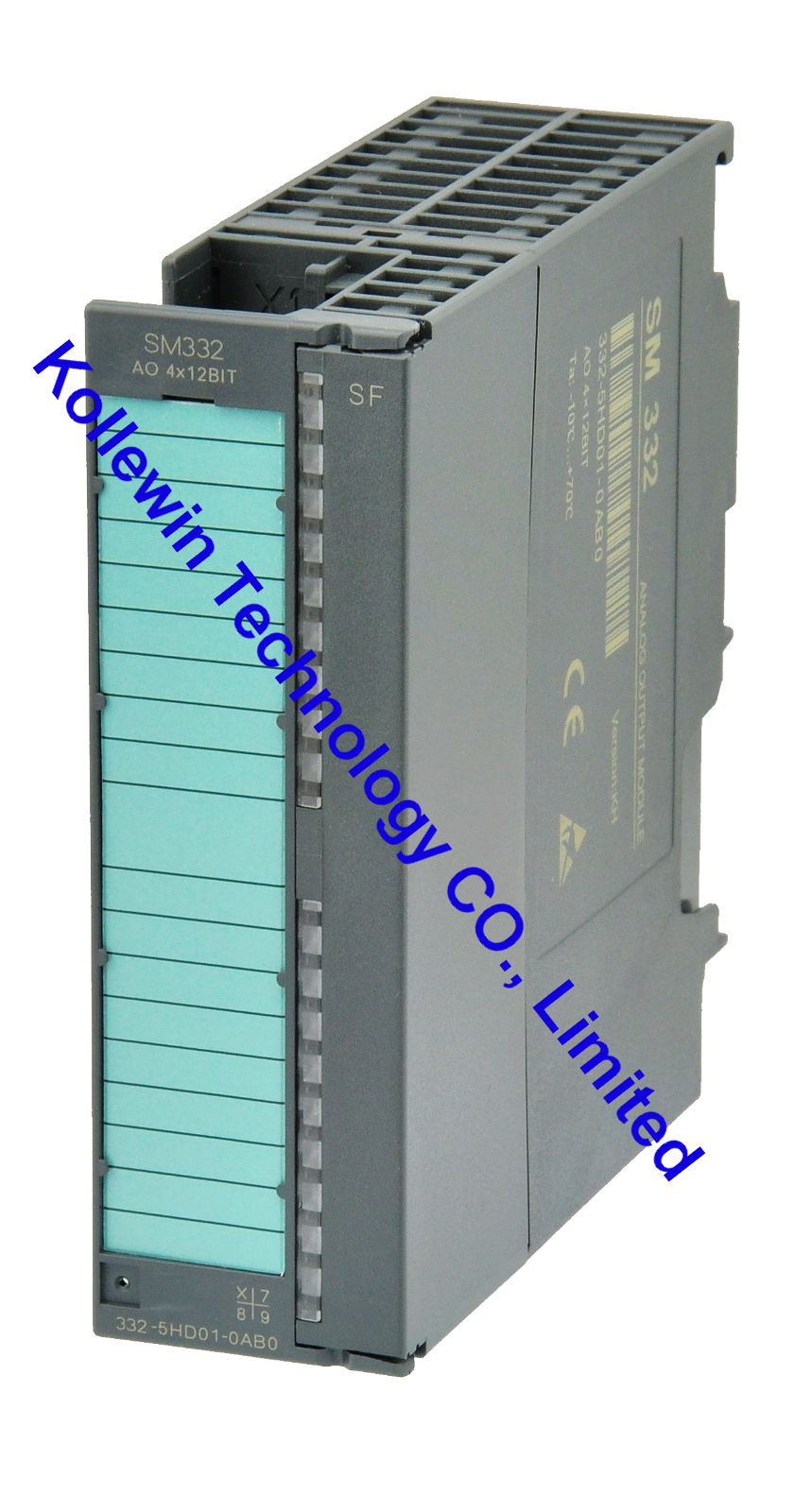
  6ES7332-5HD01-0AB0 SM332 4 AO x 12 Bits
  6ES7332-5HF00-0AB0 SM 332 8 AO x 12 BITS
SIMATIC DP  IM 153 
  6ES7153-1AA03-0XB0 SIMATIC DP, INTERFACE

IM 153-1, FOR ET 200M,

FOR MAX. 8 S7-300 MODULES
  6ES7365-0BA01-0AA0 IM 365 Rack expansion module,be deployed with a central controller and a expansion rack


More pictures for your reference:

3211bl00 321-1BL00 332-5HD01-0AB0 331-7KF02-0AB0 S7-300 322-1BH02 S7-200 321-1BL00 331-1KF01 product 3311kf01 3311kf01-00


Please feel free to contact me for any question!

Contact person: Miss Nancy

Skype: kollewin
E-mail: nancy@kollewin.com
Tel: +86-0755-26898905-8006
Website: www.kollewin.com
Jul 1 2013

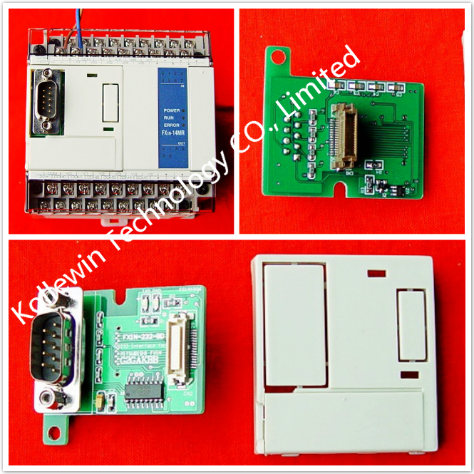
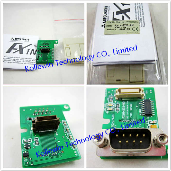
Mitsubishi FX1N-232-BD RS232 interface Board

Introduction to Mitsubishi FX1N-232-BD

The RS-232C communication board FX1N-232-BD (hereafter referred to as "232BD") is connected to the FX1S/FX1N Series PLC basic unit, and available for the applications described below.


1.1 Features of Mitsubishi FX1N-232-BD
1) Port to transfer the data using the non-procedure method between diversified RS-232C equipment.such as personal computer, bar code reader and printer
2) Port to transfer the data using a dedicated protocol between an RS-232C equipment
3) Port to connect a programming tool


1.2 Outside dimensions and name of each part to Mitsubishi FX1N-232-BD
 

30

The communication connector of the 232BD is the D-sub, 9-pin socket type. The table below shows the pin arrangement.

24

Pin No. Signal Meaning Function
1 CD Receive carrier detection Turns ON when carrier for data receive is detected.
2 RD Receive data input Receive data (RS-232C equipment to 232BD)
3 SD Send data input Send data (232BD to RS232C equipment)
4 ER Send request Turns ON when RS-232C equipment becomes ready for receive.
5 SG Signal ground Signal ground
6 DR Send enable Turns ON when send request is given to RS-232C equipment


1.3 System configuration of Mitsubishi FX1N-232-BD

For the system configuration, refer to the FX Series Communication User’s Manual offered separately.


Installation of Mitsubishi FX1N-232-BD

31


2.1 Installation procedure of Mitsubishi FX1N-232-BD
Make sure to turn off the power before installing the 232BD.
A) Communication board 232BD (function expansion board)
B) Connector for optional equipment
C)M3 screw to fix board (2 pieces) (offered as accessories of board)
D) Top cover for board (offered as an accessory of board)
E) M3 screw to fix top cover (offered as an accessory of board)
Note: This screw cannot be removed.
• Plug the communication board A) in to the connector B).
• Fix the board to the basic unit with two M3 screws C). (Tightening torque: 0.3 to 0.6 Nxm)
• Remove the top cover of the basic unit, and attach the top cover for board D) instead.
During attachment, remove D)’ with a nipper, etc. so that the connector of the board is exposed.
• Fix the top cover with an M3 screw E). (Tightening torque: 0.3 to 0.6 Nxm)
• When the FX1N-5DM is used also, refer to the handy manual offered with the FX1S/FX1N Series PLC main unit.
• Only one function expansion board is available for one FX1S/FX1N Series PLC basic unit. Never stack up two or more function expansion boards. (Even if they are stacked up, they do not function at all.) 


Specifications of Mitsubishi FX1N-232-BD

3.1 Environmental specifications of Mitsubishi FX1N-232-BD
The environmental specifications are equivalent to those of the PLC main unit. (Refer to the manual of the PLC main unit.)


3.2 Power supply specifications of Mitsubishi FX1N-232-BD
5V DC, 20 mA is supplied as the power from the PLC.


3.3 Performance specifications of Mitsubishi FX1N-232-BD

Transmission standard In conformance to RS-232C
Maximum transmission distance 15 m maximum
External equipment connection method D-sub, 9-pin type (pin socket: manufactured by JST Mfg.) with JES-9P-2A3A lock metal (inch screw thread type)
D-sub 9-pin Layout 1: CD 2: RD(RXD) 3: SD(TXD) 4: ER(DTR) 5: SG(GND)
6: DR(DSR) 7, 8, 9: NC (not used)
LED indicators  
Communication method Half duplex, bi-directional
Protocol Non-procedure, dedicated protocol 1 procedure, dedicated protocol 4 procedure, protocol for programming tool
Isolation No insulated


Our company (Kollewin Technology CO., Limited) have a new product,

named FX1N-232-BD.

It is 100% compatible with Mitsubishi original FX1N-232-BD.


Part#: FX1N-232-BD

The unit price is USD35.00/pc  buy buttom


USER'S MUNUAL PDF of Mitsubishi communication board FX1N-232-BD:

FX1N-232-BD-USER'S MANUAL


FX1N-232-BD -1 FX1N-232-BD


Specification of Mitsubishi communication board FX1N-232-BD:

Product Name Communication Board
Fit for Mitsubishi FX1N PLC
Model NO. FX1N-232-BD
Connector Type RS232C DB9 Male Plug
Voltage DC 5V
Current 20mA
Max.Transmission Distance 15M
D-sub 9-pin Layout 1:CD;2:RD(RXD);3:SD(TXD);4:ER(DTR);5:SG(GND);6:DR(DSR);7,8,9:NC(not used)
Material Plastic, Metal


Description of Mitsubishi communication board FX1N-232-BD:

  • Port to transfer the data using the non-procedure method between diversified RS-232C equipment such as personal computer, bar code reader and printer.
  • Port to transfer the data using a dedicated protocol between an RS-232C equipment.
  • Port to connect a programming tool.
  • RS232C interface boards for Mitsubishi FX1N, anti-static and anti-surge.
  • This is OEM product, not Mitsubishi original part.


More communication boards, please click below links:

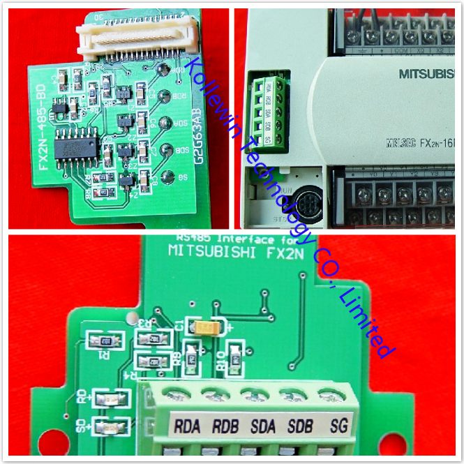
FX2N-485-BD+

FX2N-485-BD

FX2N-422-BD

FX2N-232-BD

FX1N-485-BD

FX1N-422-BD

FX3U-485-BD

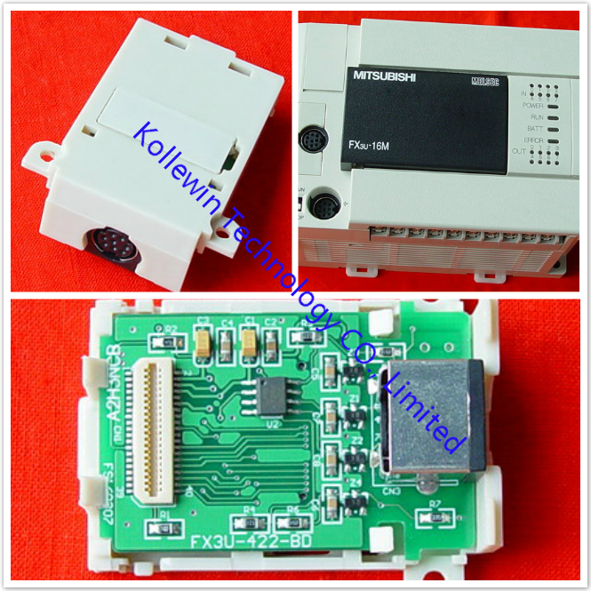
FX3U-422-BD

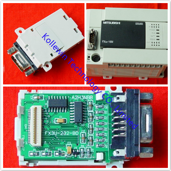
FX3U-232-BD

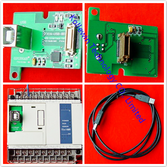
FX3U-USB-BD

FX2N-4DA


More pictures of communication board

FX1N-USB-BD-1 FX2N-485-BD+ FX3U-232-BD FX3U-422-BD FX3U-485-BD FX3U-CNV-BD FX3U-USB-BD FX2N-422-BD FX2N-USB-BD-1 FX1N-422-BD FX1N-485-BD FX2N-232-BD FX2N-485-BD


Please feel free to contact me for any question!

Contact person: Miss Nancy

Skype: kollewin
E-mail: nancy@kollewin.com
Tel: +86-0755-26898905-8006
Website: www.kollewin.com
Jun 29 2013

Mitsubishi FX2N-485-BD RS485 Board

Introduction to Mitsubishi FX2N-485-BD

The communication board FX2N-485-BD for RS485 (hereinafter referred to as “485BD”) can be connected to the base unit of the FX2N Series programmable controller to be used for the following applications.
1) Data transfer using no protocol
Data communication with diversified RS232C units including personal computers, bar code readers and printers can be performed via the RS485 (422) converter using the no protocol. In this application, data is sent or received using the data registers specified by the RS instruction. For the setting and program examples, refer to the FX Programming Manual and FX Communication User’s Manual.
2) Data transfer using the dedicated protocol
Data transfer with RS485 (422) units can be performed on the 1:N basis using the dedicated protocol.
For the contents of the dedicated protocol used in this application, refer to the FX Communication User’s Manual.
3) Data transfer using the parallel link
Data transfer with an FX2N programmable controller can be performed on the 1:1 basis for 100 auxiliary relays and 10 data registers. For the setting and program examples, refer to the FX Communication User’s Manual.
4) Data transfer using the N:N network
Data transfer with FX2N programmable controllers can be performed on the N:N basis. For the setting,the number of transferred data and program examples, refer to the FX Communication User’s Manual.


1.1 External Dimensions of Mitsubishi FX2N-485-BD


12


1.2 System Configuration of Mitsubishi FX2N-485-BD


1.2.1 No Protocol or Dedicated Protocol of Mistubishi FX2N-485-BD

13


1.2.2 Parallel Link of Mistubishi FX2N-485-BD

14


1.2.3 N:N Network of Mistubishi FX2N-485-BD

15


MUNTING AND WIRING of Mitsubishi FX2N-485-BD

2.1 Mounting Procedure to Mistubishi FX2N-485-BD

16


2.2  Cable and Terminal Resistor to connect the RS485 FX2N-485-BD


2.2.1 Cable to connect Mistubishi FX2N-485-BD
To connect the RS485 (422) unit, use a shielded twisted-pair cable.
The cable specification must be AWG 26 to 16, and the maximum tightening torque must be 0.6 N·m (6 kgf·cm). If a cable other than the AWG 26 to 16 is used, normal communication cannot be assured because the terminal may be imperfectly contacted. It is recommended to insert a cable integrated by the crimping tool into the terminal.


2.2.2 Terminal Resistor of Mistubishi FX2N-485-BD
Provide the terminal resistor at both ends of the line as described in section 2.3.2 and 2.3.3.
1) In the case of two-pair wiring, connect the terminal resistor (330W, 1/4W) between terminals SDA and SDB as well as between terminals RDA and RDB.

17
Use the resistors offered as accessories of the 485BD.
2) In the case of one-pair wiring, connect the terminal resistor (110W, 1/2W)between terminals RDA and RDB. Use the resistors offered as accessories of the 485BD.

18


2.3 Wiring of Mitsubishi FX2N-485-BD


2.3.1 Selection of Wiring of Mistubishi FX2N-485-BD
Wiring of RS485 is one-pair wiring or two-pair wiring. The wiring method is decided according to the
usage. Please select the wiring method from the table below.

19

*1 When this product is added to the system, please match the wiring to the wiring method of the system.
*2 When using 485BD with, this wiring method remember to take account of/or ignore the “echo” of the commands sent from the FX2N programmable controller.
*3 Use FX2N programmable controller and 485BD together.
*4 For excluding the combination of 485BD, please see below.

20


2.3.2 Two-pair Wiring

21

*1 R is the terminating resistance. Connect the terminating resistance (330W) between terminals SDA and SDB, and terminals RDA and RDB.
*2 The shield of the shielded twisted-pair cable must be connected to ground (100W or less). When using parallel link, ground both side. When using no protocol or dedicated protocol, ground one side.
*3 Connect terminal FG to each terminal of the programmable controller main body grounded with resistance of 100 or less. However, for the computer link unit of the A series programmable controller, see the manual of the computer link unit.
*4 When using RS232/485 or RS232/422 interface, please the use FX-485PC-IF.


2.3.3 One-pair Wiring

22

*1 R is the terminating resistance. Connect the terminating resistance (110W) between terminals RDA and RDB.
*2 The shield of the shielded twisted-pair cable must be connected to ground (100W or less). When using parallel link, ground both side. When using no protocol or dedicated protocol, ground one side.
*3 Connect terminal FG to each terminal of the programmable controller main body grounded with resistance of 100 or less. However, for the computer link unit of the A series programmable controller, see the manual of the computer link unit.
*4 When using RS232/485 or RS232/422 interface, please the use FX-485PC-IF.


SPECIFICATIONS of Mitsubishi FX2N-485-BD

3.1 General Specifications of Mitsubishi FX2N-485-BD
General specifications are the same as those for the FX2N series programmable controller.


3.2 Power Supply Specification of Mitsubishi FX2N-485-BD
5V DC, 60 mA is supplied from the programmable controller.


3.3 Specification of Mitsubishi FX2N-485-BD

 Item    Content  
 Transmission standard    Conforming to RS485 and RS422  
 Transmission distance    Max. 50 m  
 LED indicators  

 SD, RD  


Item Content
Communication
method
and protocol
N:N network Half-duplex communication
Dedicated protocol
(format 1 or format 4)
Parallel link
No protocol Full-duplex communication
Supported baud rate Dedicated protocol and no protocol: 300 ~ 19,200 (bps)
Parallel link : 19,200 (bps)
N:N network : 38,400 (bps)
Isolation No isolation


DIAGNOSTICS of Mitsubishi FX2N-485-BD

For error code of N:N network and computer link, refer to the FX Communication User’s Manual.


4.1 Common Items
1) Check the connection with the communication unit of the programmable controller and the wiring.
When the connection is unstable, the communication can not be corrected.
2) Check whether the VRRD or VRSC instruction is used in used in the program.
If it is used, delete it, turn off the power of the programmable controller, then turn it on again.
3) Each setting of communication format (D8120), parameter of programmable controller by FX-PCS/WIN-E, N:N network (D8173 to D8180) and parallel link (M8070, M8071) is suitable for the usage or it checks. The communication is not correctly done if setting is not suitable for the usage.
When each setting is changed, please turn off the power supply of the programmable controller, and turn it on again.
4) When you use FX0N-485ADP or FX-485ADP in network, please the power supply for the drive must be supplied correctly or check.


4.2 LED Check Items of Mitsubishi FX2N-485-BD
4.2.1 N:N Network
1) Check the status of the RD LED and the SD LED provided on each 485BD.
- If both of them are lit and extinguished, nothing is wrong.
- If the RD LED is lit/extinguished but the SD LED is not lit/extinguished (not lit at all), check the setting of the station No.,the baud rate (transmission rate) and the total number of salve stations.
- If the RD LED is not lit/extinguished, check the wiring.
2) Make sure that the communication error (FX2N: M8183 to M8190, FX0N: M504 to M511) in each slave station is not turned on and that the data communication flag (FX2N: M8191, FX0N: M503) is not turned off. When one of the communication error flag is turned on or if the data communication flag is turned off, check the error code of data registers (FX2N: D8211 to D8218, FX0N: D211 to D218).

For the error code, please see the FX Communication User’s Manual. 


4.3 Parallel Link
1) Check the status of the RD(RXD) LED and the SD(TXD) LED provided on each communication unit.
- If both of them are lit and extinguished, nothing is wrong.
- If the RD(RXD) LED is lit/extinguished but the SD(TXD) LED is not lit/extinguished (not lit at all),check the setting of the master station and the slave stations.
- If the RD(RXD) LED is not lit/extinguished, check the wiring.
2) Make sure that the master station and the slave stations are set correctly. If the setting is incorrect,correct it.
3) Make sure that the devices for the master station and the slave stations are handled correctly. If they are handled incorrectly, correct the program so that they are handled correctly.


4.4 Computer Link
1) Check the status of the RD(RXD) LED and the SD(TXD) LED provided on each communication unit.
- If both of them are lit and extinguished, nothing is wrong.
- If the RD(RXD) LED is lit/extinguished but the SD(TXD) LED is not lit/extinguished (not lit at all),check the setting of the station No. and the transmission rate (baud rate).
- If the RD(RXD) LED is not lit/extinguished, check the wiring and confirm the connection with the programmable controller.
2) Make sure that the communication procedure is performed correctly. If it is not performed correctly,correct the setting in the computer.
3) Check the NAK error code and programmable controller error code.
For the error code, please see the FX Communication User’s Manual.


4.5 RS Instruction
1) Check the status of the RD (RXD) LED and the SD (TXD) LED provided in an optional equipment.
- If the RD (RXD) LED is not lit while data is received or the SD (TXD) LED is not lit while data is sent, check the installation and the wiring.
- When the RD (RXD) LED is lit while data is received or the SD (TXD) LED is lit while data is sent, the installation and the wiring are correct.
2) Make sure the timing of data send/receive. For example, make sure that the counterpart equipment is ready for receive before starting to send data to it.
3) When the terminator is not used, check whether the send data capacity is equivalent to the acceptable data capacity. If the send data capacity may be changed, use the terminator.
4) Make sure that the external equipment is correctly operating.
5) Check whether the type of send data and the type of receive data are equivalent. If they are different,make them equivalent.
6) When two or more RS instructions are used in the program, make sure that only one RS instruction is actuated in one operation cycle. Never turn off the RS instruction while data is received or sent.
7) In the FX2N Series (V2.00 or later), an RS instruction is not executed if the counterpart equipment receives “NAK”.
Arrange the system so that the RS instruction is executed even if the counterpart equipment receives “NAK”.


Our company (Kollewin Technology CO., Limited) have new products.

Named FX2N-485-BD & FX2N-485-BD+ .

They are 100% compatible with Mitsubishi original FX2N-485-BD.


Part#: FX2N-485-BD

The unit price is USD21.00/pc  buy buttom


Part#:FX2N-485-BD+

The unit price is USD62.89/pc buy buttom


USER'S MUNUAL PDF of communication board FX2N-485-BD

FX2N-485-BD-USER'S MANUAL


FX2N-485-BD


FX2N-485-BD+


Specification of communication board FX2N-485-BD:

Product Name Communication Board
Fit for Mitsubishi FX2N PLC
Model NO. FX2N-485-BD
Interface Conforming to RS485 and RS422
Connector Type Mini Din 8 Pin
Voltage DC 5V
Current 60mA
Max.Transmission Distance 50M
LED Indicators SD, RD
Communication Method Half-duplex
Insulation No Insulated
Material Plastic, Metal


Description of communication board FX2N-485-BD:

  • FX2N are suitable for use with FX2N PLC's. FX2N-232-BD are used for RS-485 applications, such as communication with a PC, printer or bar code reader. and provide a second programming port which enables an operator panel (or HMI) and a programming panel to be connected to the PLC at the same time.
  • This is a Replacement of Mitsubishi FX2N-485-BD Programmable Controller.
  • This is OEM product, not Mitsubishi original part.


More communication boards, please click below links:

FX2N-485-BD+

FX2N-485-BD

FX2N-422-BD

FX2N-232-BD

FX1N-485-BD

FX1N-422-BD

FX3U-485-BD

FX3U-422-BD

FX3U-232-BD

FX3U-USB-BD

FX2N-4DA


More pictures of PLC communication board 

FX1N-USB-BD-1 FX3U-USB-BD FX3U-CNV-BD FX3U-485-BD FX3U-422-BD FX3U-232-BD FX2N-422-BD FX2N-USB-BD-1 FX1N-422-BD FX1N-485-BD FX2N-232-BD


Please feel free to contact me for any question!

Contact person: Miss Nancy

Skype: kollewin
E-mail: nancy@kollewin.com
Tel: +86-0755-26898905-8006
Website: www.kollewin.com
Jun 27 2013

Mitsubishi FX-USB-AW RS-422/USB cable

Introduction to Mitsubishi FX-USB-AW

The FX-USB-AW is a RS-422/USB conversion interface unit to connect the FX series PLC to a personal computer.

Mitsubishi FX series USB PLC programming interface conversion cable.USB/RS422 interface for Mitsubishi FX3U/FX2N/FX1N/FX0/FX0S/FX1S series PLC, with communication indicator, the largest communications range is up to 2Km.


1.1 Incorporated Items of Mitsubishi RS-422/USB FX-USB-AW interface cable
Check if the following product and items are included in the package:

Product  FX-USB-AW type interface unit
Included items USB driver software (CD-ROM)
USB cable (3m (118.1"))
User's Manual (this manual)


1.2 External Dimensions and Part Names of Mitsubishi RS-422/USB FX-USB-AW interface cable

20


Specification of Mitsubishi RS-422/USB FX-USB-AW interface cable

INSTALLATION PRECAUTIONS to Mitsubishi RS-422/USB FX-USB-AW interface cable

• Use the product in the environment within the general specifications described in PLC main unit manual (Hardware Edition).
Never use the product in areas with dust, oily smoke, conductive dusts, corrosive gas (salt air, Cl2, H2S, NH3, SO2, or NO2), flammable gas, vibrations or impacts, or expose it to high temperature, condensation, or wind and rain.
If the product is used in such a place described above, electrical shock, fire, malfunction, damage, or deterioration may be caused.


2.1 General Specifications of Mitsubishi RS-422/USB FX-USB-AW interface cable
General specifications are the same as the PLC main unit.
For general specifications, refer to the PLC main unit manual.


2.2 Performance Specifications of of Mitsubishi RS-422/USB FX-USB-AW interface cable

Current consumption 15mA / DC 5V (supplied by DC 5V power of
programmable controller)
30mA / DC 5V (supplied by USB connector of
personal computer)
Level Conversion Bidirectional between RS-422 and USB
Baud Rate 115200 bits per second, maximum
(The baud rate is different in PLC.)
Conforming standard USB2.0 (For full speed)
Signal name
(Port)
To PLC RS-422 (MINI DIN 8Pin male)
To a cable USB (MINI B plug female)


2.3 USB Cable Specifications of Mitsubishi RS-422/USB FX-USB-AW interface cable

Signal name
(Port)
To FX-USB-AW  USB (MINI B plug male)
To PC  USB (A plug male)
Length of cable  5m (196.9") at most (Included cable is 3m(118.1").)


2.4 System Requirements of Mitsubishi RS-422/USB FX-USB-AW interface cable
21

System Configuration of Mitsubishi RS-422/USB FX-USB-AW interface cable


Connected equipment and connected cable of Mitsubishi RS-422/USB FX-USB-AW interface cable

 22

23

*1 FX1NC / FX3UC Series PLC specification details for I/O, wiring,
installation, and maintenance can only be found in the Japanese Manual.
• Please refer to the specific PLC manual for a PLC not mentioned above.


Connecting Procedure of Mitsubishi RS-422/USB FX-USB-AW interface cable
1) Power off the PLC.
2) Connect the USB (MINI B plug male) connector of the USB cable to the FX-USBAW.
3) Connect the RS-422 (MINI DIN 8Pin male) connector of the FX-USB-AW to the PLC.
4) Connect the USB (A plug male) connector of the USB cable to the Personal computer.
5) Turn ON the power supply of the PLC.
6) Turn ON the power supply of the Personal computer.
7) Make sure the POWER lamp of the FX-USB-AW is lit.
(The POWER lamp of FX-USB-AW lights when power is supplied normally by the personal computer.)


Driver Installation of Mitsubishi RS-422/USB FX-USB-AW interface cable

Procedure for installing the driver is explained below.
Windows XP installation follows.
• Windows 98, Windows 98SE, Windows Millennium Edition, and Windows 2000, the installation method will vary.
Installation of the driver is canceled during the following process, the installation is not carried out correctly.
If the installation is canceled, uninstall the driver and install again.
Please refer to Chapter 7 for instructions on uninstalling the driver.

Please install the driver with the following procedure.
1)When the USB cable is connected to the personal computer, the following screen is displayed. (Installation of the software for FX-USB-AW)

24

Insert the included CD-ROM into the personal computer's CD-ROM drive.
Click [ Next > ].
The installation of the FX-USB-AW software will begin.
- If using Windows 98, Windows 98SE, Windows Millennium Edition, and
Windows 2000, A window to select the location of the installation files.
Please select the CD-ROM drive.
2) The following screen is displayed. (Only in Windows XP)

25

Click [ Continue Anyway ].
3) The following screen is displayed.

26

Click [ Finish ].
The installation of the FX-USB-AW software will finish.
- If Windows 98, Windows 98SE or Windows Millennium Edition is used,
installation of the USB Serial Port software begins, and ends automatically.
The CD-ROM can be removed from the personal computer at this time.
- If using Windows 2000 or Windows XP, proceed to step 4).

4) The following screen is displayed.

27

Click [ Next > ].
The installation of the USB Serial Port software will begin.
- If using Windows 2000, a screen to select the location of the installation
files is displayed.
Please select the CD-ROM drive.
5) The screen of 2) is displayed. (Only in Windows XP)
Click [ Continue Anyway ].
6) The following screen is displayed.

28

Click [ Finish ].
The installation of the USB Serial Port software will finish.
The CD-ROM (USB driver software) can be removed from the personal computer at this time.


USER'S MUNUAL of Mitsubishi RS-422/USB FX-USB-AW interface cable:

Mitsubishi FX-USB-AW FX3U series USB-RS422 PLC programming interface cable– USER'S MANUAL


Our company (Kollewin Technology CO., Limited) have a new product, named FX-USB-AW.

It is 100% compatible with Mitsubishi original FX-USB-AW.

Part#: FX-USB-AW

The unit price is USD35.00/pc  buy buttom

Approx. Weight: 0.3Kg
Manufacturer: Kollewin
Warranty: 1 year
Origin: China


USER'S manual of our FX-USB-AW RS-422/USB cable:

Mitsubishi RS-422USB conversion interface FX-USB-AW cable


Pictures of our compatible RS-422/USB FX-USB-AW interface cable:

FX-USB-AW 1


Introduction to our compatible RS-422/USB FX-USB-AW interface cable

Mitsubishi FX series USB PLC programming interface conversion cable.USB/RS422 interface for Mitsubishi FX3U/FX2N/FX1N/FX0/FX0S/FX1S series PLC, 2.5 meters, with communication indicator, the largest communications range is up to 2Km.


Summary of our compatible RS-422/USB FX-USB-AW interface cable

FX-USB-AW is the programming cable in which USB interface provided both the serial connection and RS422 signal conversion. Under the control of computer-driven driver, the programming cable makes it possible for the computer's USB interface to simulate the traditional serial (known as COM interface), thus various existing programming software such as communications software, monitoring software and other applications can be normally used. The working power supply of this cable is directly from the USB port, but not the PLC programming interface. The two-color LED on the converter box indicates data’s transceiving status.

FX-USB-AW is applicable to the FX3U series PLC which has the MD8F radio socket of Mitsubishi, such as FX3U/FX2N/FX1N/FX0/FX0N/FX0S/FX1S, and it can substitute the FX-232AW module. The largest communications distance is two kilometers.

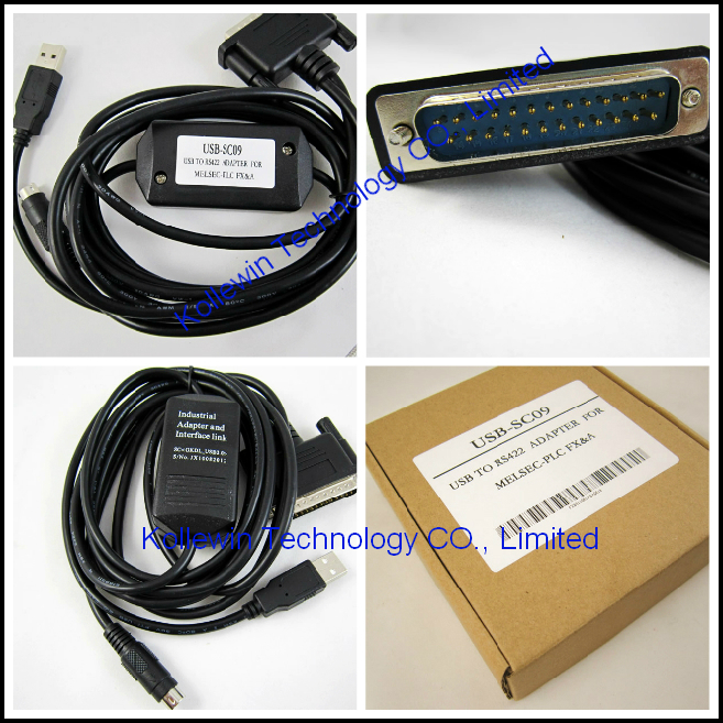
Do choose the USB-SC09 programming cable, for A and all FX series Mitsubishi PLC (including the old products FX2/FX2C).

USB-SC09

USB-SC09-FX


Principle and figure structure of our RS-422/USB FX-USB-AW cable

16

FX-USB-AW programming cable simulate USB port as traditional serial port (usually COM3), which enables existing programming software(GX Developer)

to communicate through simulated traditional port and PLC devices.
 

Features and technological index of FX-USB-AW interface cable

● Support FX-USB-AW operating system: Windows2000/XP (WinNT4/95/98/Me/DOS not included )
● Support FX-USB-AW programming software version: FXGP / WIN V1.0, GPP V4.0, GX Developer V7.0 and above.● Fully compatible with USB V1.1 norms and USB CDC V1.1
● USB-bus powered, with current consumption of 50 mA
● Baud rate: 300 bps ~ 1Mbps automatically adapt to the standard baud rate
● Support UART data format: data bits: 7-8; stop bit: 1, 2; check-bit: odd / even / no parity
● Support long-distance communications, the largest communications is two kilometers (9600 bps)
● Each PC only supports one USB cable programming
● Working temperature: -20 ~ +75 ℃
● Cable length: 2.5m; Color: black


System requirement of our RS-422/USB FX-USB-AW interface cable

Please make sure your PC is IBM PC compatible and has the following system
requirements before using the USB programming cable.
● Intel is compatible with 586DX4-100MHz CPU or higher
● A standard USB port (4-pin A plug)
● Operating system is Windows2000 or Windows XP
17
 
Setting of GX Developer
After completing Driver installation, the corresponding COM port for the FX-USB-AW programming cable will be displayed in the “Device Manager” of Window.
The next step is just to choose this COM port in the programming software and other application software and keep other communication parameters as in the Default settings.
And the following steps are exactly the same as the traditional programming cables with RS232 interfaces. Note: DB25M plugs and MD8M plugs of the RS422 interface can not be used at the same time. 
Open the main windows form(GX Developer), choose “Online” menu then click “Transfer Setup…” and will appear “Transfer Setup” window.
Click “Serial” button of the PC side I/F, and choice the COM X interface as it in the Device Manager.

18


About Long Distance Communication
For FX-USB-AW,The largest communication distance is up to two kilometers
(9600 bps).The user must follow the self-made plan to extend cable.
Transmission Line should be 0.22mm or more, twisted pair wire. When the
distance is over 2,000 m,RS422 repeater could be installed to extend the
distance.
Please Note: USB interface cable cannot be extended.
 
19
 
Due to internal resistance have been installed in FX-USB-AW and the PLC, no
external terminal resistance is needed.


Usage of our RS-422/USB FX-USB-AW interface cable:

USB device drivers should be installed before using FX-USB-AW programming cable, which are available on the CD-ROM sold together with the cable. And for the specific installation steps, please refer to the instruction files on the CD-ROM drivers, and details are not necessarily listed here.

After completing Driver installation, the corresponding COM port for the FX-USB-AW programming cable will be displayed in the “Device Manager” of Window. The step next is just to choose this COM port in the programming software and other application software and keep other communication parameters as in the Default settings. And the following steps are exactly the same as in the traditional programming cables with RS232 interfaces.

Long-distance communications:

the largest communications range between the FX-USB-AW programming cable and the PLC is up to two kilometers (9600 bps)。The user must follow the self-made plans to extend cable. Transmission Line should be 0.22mm2 or more, twisted pair wire. When the distance is over 2,000 m , RS422 repeater could be installed to extend the distance.

Please Note: USB interface cable cannot be extended.


More compatible Mitsubishi cable & communication board

ES-ETH-SC09-NEW

FX-USB-AW

USB-SC09

USB-SC09-FX

SC-09+

SC-10

USB-QC30R2

FX2N-485-BD+

FX2N-485-BD

FX2N-422-BD

FX2N-232-BD

FX1N-485-BD

FX1N-422-BD

FX3U-485-BD

FX3U-422-BD

FX3U-232-BD

FX3U-USB-BD

FX2N-4DA


Pictures for your reference:

USB-SC09-FX_1 ES-ETH-SC09 1 USB-QC30R2 1 USB-SC09_1


Of course, we also can supply some compatible PLC Programming cables of ohter brands, such as Siemens/OMRON/Panasonic/GE/Fuji/Schneider/Allen-Bradley/Delta/Proface…

CP5611

CP5611-A2

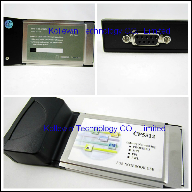
CP5512

CP5512EXP-NEW

PC Adapter CN-NEW

ES-ETH-PPI-NEW

ETH Adapter CN-NEW

USB/PPIM+

PC/PPI

PC/PPI+

USB/MPI+ V4.0

USB/MPI+ V2.0

PC/MPI+ including RS232 cable

PC/MPI

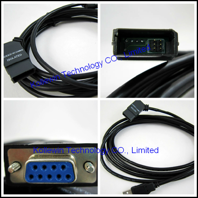
LOGO!USB-CABLE

LOGO!PC-CABLE

MPI extension cable

PC/TTY

1747-PIC

1747-UIC

1747-CP3

USB-1747-CP3 

1761-CBL-PM02

USB-1761-CBL-PM02


More pictures:

USB-MPI V5.0_1 USB-MPI+V4.0_1 USB-MPI+V2.0_1 logo-PC cable_1 logo-usb cable_1 CP5512E_1 CP5611-A2_1 CP5512_1 PC-TTY_1 1747-UIC_1 0CB20-1 V6.0_1 1747-PIC_1 USB-1761-CBL-PM02_1 IC690ACC901_1 IC690USB901_1 TSXPCX3030_1 USB-CIF02_1 USB-CN226 _1


Please feel free to contact me for any question!

Contact person: Miss Nancy

Skype: kollewin
E-mail: nancy@kollewin.com
Tel: +86-0755-26898905-8006
Website: www.kollewin.com
Jun 27 2013

Siemens 6ES7307-1KA02-0AA0 Power Supply

Introduction to 10A PS307 6ES7307-1KA02-0AA0

SIMATIC S7-300 STABILIZED POWER SUPPLY PS307 INPUT: 120/230 V AC OUTPUT: DC 24 V DC/10 A


Technical data sheet of 10A PS307 6ES7307-1KA02-0AA0

       32
SIMATIC S7-300 STABILIZED POWER SUPPLY PS307 INPUT: 120/230 V AC OUTPUT: DC 24 V DC/10 A
Technical specifications  
Product PS 307
Power supply, type 24 V/10 A
Input  
Input 1-phase AC
Supply voltage / 1 / at AC / nominal value 120 V
Supply voltage / 2 / at AC / nominal value 230 V
Voltage range  
  • Note
Automatic range selection
Input voltage / 1 / at AC 85…132 V
Input voltage / 2 / at AC 170…264 V
Wide-range input No
Overvoltage resistance 2.3 × Vin rated, 1.3 ms
Mains buffering at Iout rated, min. 20 ms
Mains buffering at Vin = 93/187 V
Rated line frequency 50/60 Hz
Rated line range 47…63 Hz
Input current / at nominal level of the input voltage 120 V 4.2 A
Input current / at nominal level of the input voltage 230 V 1.9 A
Switch-on current limiting (+25 °C), max. 55 A
Duration of current limiting / at 25 °C / maximum 3 ms
I²t, max. 3.3 A²·s
Built-in incoming fuse T 6.3 A/250 V (not accessible)
Protection in the mains power input (IEC 898) Recommended miniature circuit breaker: from 10 A, characteristic C
Output  
Output Controlled, isolated DC voltage
Rated voltage Vout DC 24 V
Total tolerance, static ± 3 %
Static mains compensation, approx. 0.1 %
Static load balancing, approx. 0.5 %
Residual ripple peak-peak, max. 50 mV
Residual ripple peak-peak, typ. 15 mV
Spikes peak-peak, max. (bandwidth: 20 MHz) 150 mV
Spikes peak-peak, typ. (bandwidth: 20 MHz) 60 mV
Product feature / output voltage adjustable No
Output voltage setting -
Status display Green LED for 24 V OK
On/off behavior No overshoot of Vout (soft start)
Startup delay, max. 2 s
Voltage rise, typ. 10 ms
Rated current value Iout rated 10 A
Current range 0…10 A
delivered active power / typ. 240 W
short-term overload current / at short-circuit during run-up / typical 38 A
Duration of overloading ability for excess current / on short-circuiting during the start-up 80 ms
short-term overload current / at short-circuit during operation / typical 38 A
Duration of overloading ability for excess current / on short-circuiting during the operational phase 80 ms
Parallel switching for enhanced performance Yes
Efficiency  
Efficiency at Vout rated, Iout rated, approx. 90 %
Power loss at Vout rated, Iout rated, approx. 27 W
Closed-loop control  
Dynamic mains compensation (Vin rated ±15 %), max. 0.1 %
Dynamic load smoothing (Iout: 50/100/50 %), Uout ± typ. 2 %
Setting time / maximum 0.1 ms
Protection and monitoring  
Output overvoltage protection Additional control loop, shutdown at < 28.8 V, automatic restart
Current limitation 11…12 A
Characteristic feature of the output / short-circuit protected Yes
Short-circuit protection Electronic shutdown, automatic restart
Enduring short circuit current / Effective level / maximum 12 A
Overload/short-circuit indicator -
Safety  
Primary/secondary isolation Yes
Potential separation Safety extra-low output voltage Uout acc. to EN 60950-1 and EN 50178
Protection class Class I
stray current / maximum 3.5 mA
stray current / typical 0.6 mA
CE mark Yes
UL/CSA approval Yes
UL/cUL (CSA) approval cULus-Listed (UL 508, CSA C22.2 No. 142), File E143289, UL 1604 Class I Div. 2 Group A, B, C, D, File E330455
Explosion protection ATEX (EX) II 3G Ex nA II T4; UL 1604 Class I, Div. 2, Group ABCD
FM approval Class I, Div. 2, Group ABCD, T4
CB approval No
Marine approval In S7-300 system
Degree of protection (EN 60529) IP20
EMC  
Emitted interference EN 55022 Class B
Supply harmonics limitation EN 61000-3-2
Noise immunity EN 61000-6-2
Operating data  
Ambient temperature / in operation 0…60 °C
  • Note
with natural convection
Ambient temparature / on transport -40…+85 °C
Ambient temparature / in storage -40…+85 °C
Humidity class according to EN 60721 Climate class 3K3, no condensation
Mechanics  
Connection technology screw-type terminals
Connections / Supply input L, N, PE: 1 screw terminal each for 0.5 … 2.5 mm² single-core/finely stranded
Connections / Output L+, M: 4 screw terminals each for 0.5 … 2.5 mm²
Connections / Auxiliary -
Width / of the housing 80 mm
Height / of the housing 125 mm
Depth / of the housing 120 mm
Installation width 80 mm
Mounting height 205 mm
Weight, approx. 0.8 kg
Product feature / of the housing / housing for side-by-side mounting Yes
Type of mounting / wall mounting No
Type of fixing / cap rail mounting No
Type of mounting / S7-300 rail mounting Yes
Installation Can be mounted onto S7 rail
Mechanical accessories Mounting adapter for standard mounting rail (6EP1971-1BA00)
Other information Specifications at rated input voltage and ambient temperature +25 °C (unless otherwise specified)


User's manual PDF of Power Supply PS307 10A 6ES7307-1KA02-0AA0:

User's manual 6ES7307-1KA02-0AA0 POWER SUPPLY PS307 10 A_PDF


Our company (Kollewin Technology CO., Limited) have a new product,

named 6ES7307-1KA02-0AA0,

it is 100% compatible with Siemens original part.

Part#: 6ES7307-1KA02-0AA0

Unit price:USD140.00/pc  buy buttom
Description: S7-300 10 A power suppky
Manufacturer: Kollewin
Approx. Weight: 1.2 Kg
Warranty: 1 year
Origin: China


Here, PS307 5A power supply

6ES7307-1EA01-0AA0


Technical data sheet of our 10A PS307 6ES7307-1KA02-0AA0

Model

PS307 power,10A

Type

10A

Description

Max.output current:10A;Output voltage:24V DC;


Connect single-phase AC system(input voltage:120/230VAC,50/60Hz)

The isolation characteristic is stalbe;

Can be used as a load power supply

The rated input voltage value 120/230VAC
Voltage range

85~132V/170~ 264 V AC

System frequency value 50 Hz ~ 60 Hz
Permissible error 47 Hz ~ 63 Hz
The rated input current value At 230V 1.8A
At 120V 4.1A
Starting current < 55 A, < 3 ms
(at starting current) 3.3A2s
Output voltage value 24VDC
Permissible error 24V±3%
Rise value Max:1.5 S,typical value:80ms
The rated output current value 10A,can not be connected by Parallel connection

Short circuit protection

Electronic shutoff, cold start automatically

Residual ripple

Max:150mVpp

Discharge current

< 3.5 mA (typical value:0.5 mA)

Efficiency

About 87%
Power consumption typical value:34W
Output voltage have indicating lamp. Normally at 24V,green indicating lamp is working
Dimensions(W×H×D)(mm) 200×125×120
Weight About 1.2Kg
Order number  307-1KA01-0AA0


Picture of our 10A PS307 6ES7307-1KA02-0AA0

6ES7 307-1KA01-0AA0_1

 
More compatible Siemens accessories we can offer:
Model Short Description
6ES7 972-0BA12-0XA0 Profibus connector,without PG port,90 degree
6ES7 972-0BB12-0XA0 Profibus connector,with PG port,90 degree
6ES7 972-0BA41-0XA0 Profibus Connector,without PG port,35 degree
6ES7 972-0BB41-0XA0 Profibus Connector,with PG port,35 degree
6ES7 972-0BA42-0XA0 Profibus Connector,without PG port,35 degree
6ES7 972-0BB42-0XA0 Profibus Connector,with PG port,35 degree
6ES7 972-0BA50-0XA0 DP ,90 DEGREE ,NO PROGRAMMING INTER,FAST CONNECT
6ES7 972-0BB50-0XA0 DP ,90 DEGREE ,WITH PROGRAMMING INTER,FAST CONNECT
6ES7 972-0BA52-0XA0  
6ES7 972-0BB52-0XA0  
6GK1500-0FC00  
6GK1500-0FC10  
6GK1500-0EA02  
6ES7 291-8GF23 Plus memory card (capacity of 64K)
6ES7 290-6AA20  
6ES7 307-1EA01-0AA0 power supply,5A,24VDC output,120/230VAC input
6ES7 307-1KA02-0AA0 SIMATIC S7-300


STABILIZED POWER SUPPLY PS307


INPUT: 120/230 V AC


OUTPUT: DC 24 V DC/10 A
6ES7 390-1AF30-0AA0 S7-300 PLC rail,530 MM length.
6ES7 390-1AJ30-0AA0 S7-300 PLC rail,830 MM length.
6ES7 390-1AB60-0AA0 S7-300 PLC rail,160 MM length.
6ES7 390-1AE80-0AA0 S7-300 PLC rail,482 MM length.
6ES7 390-1BC00-0AA0 S7-300 PLC rail,2000 MM length.
6ES7195-1GA00-0XA0 hot plug rail,483mm
6ES7195-1GF30-0XA0 hot plug rail,530mm
6ES7195-1GG30-0XA0 hot plug rail,620mm
6ES7195-1GC00-0XA0 hot plug rail,2000mm
6XV1-830-0EH10 Profibus cable
6XV1840-2AH10 profibus cable
6XV1830-3EH10 profibus cable


More details of S7-300 & S7-400 front connector:

​20-PIN    6ES7 392-1AJ00-0AA0


40-PIN   6ES7 392-1AM00-0AA0


48-PIN   6ES7 492-1AL00-0AA0


Not made by Siemens,but the quality is 100% guaranteed,1 year warranty.

All of our compatible products are tested one by one by our Engineer department before shipment.


More compatible Siemens accessories we can offer:

6ES7 972-0BA12-0XA0 6GK1500-0EA02-1 6ES7 972-0BA41-0XA0_1 6ES7 972-0BB41-0XA0_1 6ES7 972-0BA42-0XA0_1 6ES7 972-0BB42-0XA0_1 6ES7 972-0BA52-0XA0_1 6ES7 972-0BB52-0XA0_1 6GK1500-0FC00_1 6GK1500-0FC10_1 6XV1830-0EH10_1 6ES7 307-1KA01-0AA0_1 6ES7 390-1AE80-0AA0-1 6ES7 972-0BB12-0XA0 6ES7 492-1AL00-0AA0_1 6ES7 392-1AJ00-0AA0_1 6ES7 392-1AM00-0AA0_2


Please feel free to contact me for any question!

Contact person: Miss Nancy

Skype: kollewin
E-mail: nancy@kollewin.com
Tel: +86-0755-26898905-8006
Website: www.kollewin.com
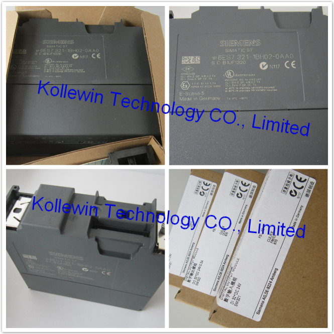
 

Jun 26 2013

6ES7 307-1EA01-0AA0 Siemens power supply

Introduction to 6ES7307-1EA01-0AA0

SIMATIC S7-300 STABILIZED POWER SUPPLY PS307 INPUT: 120/230 V AC OUTPUT: DC 24 V DC/5 A


Technical data sheet of 6ES7307-1EA01-0AA0

    33

SIMATIC S7-300 STABILIZED POWER SUPPLY PS307 INPUT: 120/230 V AC OUTPUT: DC 24 V DC/5 A
Technical specifications  
Product PS 307
Power supply, type 24 V/5 A
Input  
Input 1-phase AC
Supply voltage / 1 / at AC / nominal value 120 V
Supply voltage / 2 / at AC / nominal value 230 V
Voltage range  
  • Note
Automatic range selection
Input voltage / 1 / at AC 85…132 V
Input voltage / 2 / at AC 170…264 V
Wide-range input No
Overvoltage resistance 2.3 × Vin rated, 1.3 ms
Mains buffering at Iout rated, min. 20 ms
Mains buffering at Vin = 93/187 V
Rated line frequency 50/60 Hz
Rated line range 47…63 Hz
Input current / at nominal level of the input voltage 120 V 2.3 A
Input current / at nominal level of the input voltage 230 V 1.2 A
Switch-on current limiting (+25 °C), max. 20 A
Duration of current limiting / at 25 °C / maximum 3 ms
I²t, max. 1.2 A²·s
Built-in incoming fuse T 3,15 A/250 V (not accessible)
Protection in the mains power input (IEC 898) Recommended miniature circuit breaker: from 6 A, characteristic C
Output  
Output Controlled, isolated DC voltage
Rated voltage Vout DC 24 V
Total tolerance, static ± 3 %
Static mains compensation, approx. 0.1 %
Static load balancing, approx. 0.5 %
Residual ripple peak-peak, max. 50 mV
Residual ripple peak-peak, typ. 10 mV
Spikes peak-peak, max. (bandwidth: 20 MHz) 150 mV
Spikes peak-peak, typ. (bandwidth: 20 MHz) 20 mV
Product feature / output voltage adjustable No
Output voltage setting -
Status display Green LED for 24 V OK
On/off behavior No overshoot of Vout (soft start)
Startup delay, max. 2 s
Voltage rise, typ. 10 ms
Rated current value Iout rated 5 A
Current range 0…5 A
delivered active power / typ. 120 W
short-term overload current / at short-circuit during run-up / typical 20 A
Duration of overloading ability for excess current / on short-circuiting during the start-up 100 ms
short-term overload current / at short-circuit during operation / typical 20 A
Duration of overloading ability for excess current / on short-circuiting during the operational phase 100 ms
Parallel switching for enhanced performance Yes
Efficiency  
Efficiency at Vout rated, Iout rated, approx. 87 %
Power loss at Vout rated, Iout rated, approx. 18 W
Closed-loop control  
Dynamic mains compensation (Vin rated ±15 %), max. 0.1 %
Dynamic load smoothing (Iout: 50/100/50 %), Uout ± typ. 1 %
Load step setting time 50 to 100%, typ. 0.3 ms
Load step setting time 100 to 50%, typ. 0.3 ms
Protection and monitoring  
Output overvoltage protection Additional control loop, shutdown at < 28.8 V, automatic restart
Current limitation 5.5…6.5 A
Characteristic feature of the output / short-circuit protected Yes
Short-circuit protection Electronic shutdown, automatic restart
Enduring short circuit current / Effective level / maximum 7 A
Safety  
Primary/secondary isolation Yes
Potential separation Safety extra-low output voltage Uout acc. to EN 60950-1 and EN 50178
Protection class Class I
stray current / maximum 3.5 mA
stray current / typical 0.5 mA
CE mark Yes
UL/CSA approval Yes
UL/cUL (CSA) approval cULus-Listed (UL 508, CSA C22.2 No. 142), File E143289, UL 1604 Class I Div. 2 Group A, B, C, D, File E330455
Explosion protection ATEX (EX) II 3G Ex nA II T4; UL 1604 Class I, Div. 2, Group ABCD
FM approval Class I, Div. 2, Group ABCD, T4
CB approval No
Marine approval In S7-300 system
Degree of protection (EN 60529) IP20
EMC  
Emitted interference EN 55022 Class B
Supply harmonics limitation EN 61000-3-2
Noise immunity EN 61000-6-2
Operating data  
Ambient temperature / in operation 0…60 °C
  • Note
with natural convection
Ambient temparature / on transport -40…+85 °C
Ambient temparature / in storage -40…+85 °C
Humidity class according to EN 60721 Climate class 3K3, no condensation
Mechanics  
Connection technology screw-type terminals
Connections / Supply input L, N, PE: 1 screw terminal each for 0.5 … 2.5 mm² single-core/finely stranded
Connections / Output L+, M: 3 screw terminals each for 0.5 … 2.5 mm²
Connections / Auxiliary -
Width / of the housing 60 mm
Height / of the housing 125 mm
Depth / of the housing 120 mm
Installation width 60 mm
Mounting height 205 mm
Weight, approx. 0.6 kg
Product feature / of the housing / housing for side-by-side mounting Yes
Type of mounting / wall mounting No
Type of fixing / cap rail mounting No
Type of mounting / S7-300 rail mounting Yes
Installation Can be mounted onto S7 rail
Mechanical accessories Mounting adapter for standard mounting rail (6EP1971-1BA00)
Other information Specifications at rated input voltage and ambient temperature +25 °C (unless otherwise specified)


User's manual PDF of Power Supply PS307 5A 6ES7307-1EA01-0AA0:


User's manual 6ES7307-1EA01-0AA0 POWER SUPPLY PS307 5 A_PDF


Our company (Kollewin Technology CO., Limited) have a new product,

named 6ES7307-1EA01-0AA0,

it is 100% compatible with Siemens original part.

Part#: 6ES7307-1EA01-0AA0

Unit price:USD93.00/pc  buy buttom
Description: S7-300 5A power suppky
Manufacturer: Kollewin
Approx. Weight: 0.75 Kg
Warranty: 1 year
Origin: China


Here, PS307 10A power supply

6ES7307-1KA02-0AA0


Technical data sheet of our 5A PS307 6ES7307-1EA01-0AA0 

Model

PS307 power,5A

Type

5A

Description

Max.output current:5A;


Output voltage:24V DC;

Connect single-phase AC system(input voltage:120/230VAC,50/60Hz)

The isolation characteristic is stable;

Can be used as a load power supply.


The rated input voltage value 120/230VAC
Voltage range

85~132V/170~264V AC

System frequency value 50 Hz ~ 60 Hz
Permissible error 47Hz ~ 63 Hz
The rated input current value At 230V 1.3A
At 120V 2.1A
Starting current < 45 A, < 3 ms
I2t(at starting current) 1.2A2s
Output voltage value 24VDC
Permissible error 24V±3%
Rise value <2 S,typical value:60ms
The rated output current value 5A,can not be connected by Parallel connection

Short circuit protection

Electronic shutoff, cold start automatically

Residual ripple

Max:150mVpp

Discharge current

< 3.5 mA (typical value:0.3 mA)

Efficiency

About 87%
Power consumption typical value:18W
Output voltage have indicating lamp. Normally at 24V,green indicating lamp is working
Dimensions(W×H×D)


(mm)

80×125×120
Weight About 750g
Order number  307-1EA00-0AA0


Picture of our 5A PS307 6ES7307-1EA01-0AA0

6ES7 307-1EA01-0AA0


More compatible Siemens accessories we can offer:
Model Short Description
6ES7 972-0BA12-0XA0 Profibus connector,without PG port,90 degree
6ES7 972-0BB12-0XA0 Profibus connector,with PG port,90 degree
6ES7 972-0BA41-0XA0 Profibus Connector,without PG port,35 degree
6ES7 972-0BB41-0XA0 Profibus Connector,with PG port,35 degree
6ES7 972-0BA42-0XA0 Profibus Connector,without PG port,35 degree
6ES7 972-0BB42-0XA0 Profibus Connector,with PG port,35 degree
6ES7 972-0BA50-0XA0 DP ,90 DEGREE ,NO PROGRAMMING INTER,FAST CONNECT
6ES7 972-0BB50-0XA0 DP ,90 DEGREE ,WITH PROGRAMMING INTER,FAST CONNECT
6ES7 972-0BA52-0XA0  
6ES7 972-0BB52-0XA0  
6GK1500-0FC00  
6GK1500-0FC10  
6GK1500-0EA02  
6ES7 291-8GF23 Plus memory card (capacity of 64K)
6ES7 290-6AA20  
6ES7 307-1EA01-0AA0 power supply,5A,24VDC output,120/230VAC input
6ES7 307-1KA02-0AA0 SIMATIC S7-300


STABILIZED POWER SUPPLY PS307


INPUT: 120/230 V AC


OUTPUT: DC 24 V DC/10 A
6ES7 390-1AF30-0AA0 S7-300 PLC rail,530 MM length.
6ES7 390-1AJ30-0AA0 S7-300 PLC rail,830 MM length.
6ES7 390-1AB60-0AA0 S7-300 PLC rail,160 MM length.
6ES7 390-1AE80-0AA0 S7-300 PLC rail,482 MM length.
6ES7 390-1BC00-0AA0 S7-300 PLC rail,2000 MM length.
6ES7195-1GA00-0XA0 hot plug rail,483mm
6ES7195-1GF30-0XA0 hot plug rail,530mm
6ES7195-1GG30-0XA0 hot plug rail,620mm
6ES7195-1GC00-0XA0 hot plug rail,2000mm
6XV1-830-0EH10 Profibus cable
6XV1840-2AH10 profibus cable
6XV1830-3EH10 profibus cable


More details of S7-300 & S7-400 front connector:

​20-PIN    6ES7 392-1AJ00-0AA0


40-PIN   6ES7 392-1AM00-0AA0


48-PIN   6ES7 492-1AL00-0AA0


Not made by Siemens,but the quality is 100% guaranteed,1 year warranty.

All of our compatible products are tested one by one by our Engineer department before shipment.


More compatible Siemens accessories we can offer:

6ES7 972-0BA12-0XA0 6GK1500-0EA02-1 6ES7 972-0BA41-0XA0_1 6ES7 972-0BB41-0XA0_1 6ES7 972-0BA42-0XA0_1 6ES7 972-0BB42-0XA0_1 6ES7 972-0BA52-0XA0_1 6ES7 972-0BB52-0XA0_1 6GK1500-0FC00_1 6GK1500-0FC10_1 6XV1830-0EH10_1 6ES7 307-1KA01-0AA0_1 6ES7 390-1AE80-0AA0-1 6ES7 972-0BB12-0XA0 6ES7 392-1AJ00-0AA0_1 6ES7 392-1AM00-0AA0_2 6ES7 492-1AL00-0AA0_1 6ES7 972-0BB50-0XA0 6ES7 972-0BA50-0XA0

Jun 25 2013

SIEMENS 6GK1500-0EA02 profibus connector

Introduction to profibus connector 6GK1500-0EA02

PB BUS CONNECTOR WITH AXIAL CABLE OUTLET F.INDUSTR. PC, SIMATIC OP, OLM; TRANSMISSION RATE 12 MBIT/S; TERMINATING RESISTOR WITH SEPARATING FUNCTION, METAL HOUSING


Technical data sheet of profibus connector 6GK1500-0EA02

     17
PB BUS CONNECTOR WITH AXIAL CABLE OUTLET F.INDUSTR. PC, SIMATIC OP, OLM; TRANSMISSION RATE 12 MBIT/S; TERMINATING RESISTOR WITH SEPARATING FUNCTION, METAL HOUSING
Transfer rate  
  • with PROFIBUS
9.6 kbit/s…12 Mbit/s
Interfaces  
Number of electrical connections  
  • for PROFIBUS cables
2
  • for network components and terminal equipment
1
Design of the electrical connection  
  • for network components and terminal equipment
9-pin Sub-D plug
Design of the electrical connection / FastConnect No
Mechanical data  
Material / of the enclosure metal
Design, dimensions and weight  
Width 15 mm
Height 57 mm
Depth 39 mm
Net weight 100 g
Permitted ambient conditions  
Ambient temperature  
  • during operating
0…60 °C
  • during storage
-25…+80 °C
  • during transport
-25…+80 °C
Relative humidity / at 25 °C / without condensation / during operating / maximum 75 %
Protection class IP IP20
Product properties, functions, components / general  
Product feature / [not supplied - silicon-free] Yes
Product component  
  • PG connection socket
No
  • strain relief
Yes
Standards, specifications, approvals  
Verification of suitability  
  • RoHS conformity
Yes
  • UL-registration
No


USER'S manual PDF of profibus connector 6GK1500-0EA02

PROFUBUS connector 6GK1500-0EA02 with AXIAL cable outlet

RS485-Profibus-Connectors

PROFIBUS -NETWORK-manual


Our company (Kollewin Technology CO., Limited) have a new product,

named 6GK1500-0EA02.

It is 100% compatible with Siemens original part.


Part#: 6GK1500-0EA02

EX-Work Price: $24.00 /pc       buy buttom

6GK1500-0EA02-1


Description to our compatible PB connector 6GK1500-0EA02

Product
Article Number 6GK1500-0EA02
Product Description PB BUS CONNECTOR
WITH AXIAL CABLE OUTLET
F.INDUSTR. PC, SIMATIC OP, OLM;
TRANSMISSION RATE 12 MBIT/S;
TERMINATING RESISTOR WITH
SEPARATING FUNCTION,
METAL HOUSING
Price p. item*
*Recommended Retail Price
Price On Request
Customer Price Price On Request
Country of origin CN
Export Control Regulations AL: N / ECCN: N
Delivery Time 3-5 Days
Net Weight (kg) 0.049 Kg
Quantity Unit  Piece
Packaging Type Piece
Packaging Quantity 1
Minimum order quantity 1


More profibus connectors we can offer as follows:

6ES7972-0BA12-0XA0   EX-Work Price: $16.00 /pc       buy buttom

100pcs or more $12.00
200pcs or more $11.00
300pcs or more $10.00
400pcs or more $9.00
500pcs or more $8.00

6ES7972-0BB12-0XA0   EX-Work Price: USD16.00 /pc        buy buttom


100pcs or more $12.00
200pcs or more $11.00
300pcs or more $10.00
400pcs or more $9.00
500pcs or more $8.00

6ES7 972-0BA12-0XA0 6ES7 972-0BB12-0XA0


6ES7972-0BA41-0XA0   

Profibus Connector,without PG port,35 degree    @USD16.00/pc    buy buttom

6ES7972-0BB41-0XA0   

Profibus Connector,with PG port,35 degree          @USD16.00/pc     buy buttom

100pcs or more $12.00
200pcs or more $11.00
300pcs or more $10.00
400pcs or more $9.00
500pcs or more $8.00

6ES7 972-0BA41-0XA0_1 6ES7 972-0BB41-0XA0_1


6ES7972-0BA42-0XA0    

Profibus Connector,without PG port,35 degree      @USD16.90/pc     buy buttom

6ES7972-0BB42-0XA0    

Profibus Connector,with PG port,35 degree          @USD16.90/pc      buy buttom

100pcs or more $12.00
200pcs or more $11.00
300pcs or more $10.00
400pcs or more $9.00
500pcs or more $8.50

6ES7 972-0BA42-0XA0_1 6ES7 972-0BB42-0XA0_1


6ES7972-0BA50-0XA0   @USD20.00/pc   buy buttom

Profibus Connector,without PG port, 90 degree

6ES7972-0BB50-0XA0    @USD20.00/pc   buy buttom

Profibus Connector,with PG port, 90 degree

6ES7 972-0BA50-0XA0 6ES7 972-0BB50-0XA0
 

6ES7972-0BA52-0XA0   @USD21.00/pc   buy buttom

Profibus Connector,without PG port, 90 degree

100pcs or more $18.00
200pcs or more $17.00
300pcs or more $16.00
400pcs or more $15.00
500pcs or more $14.00

6ES7972-0BB52-0XA0   @USD24.00/pc   buy buttom

Profibus Connector,with PG port, 90 degree

100pcs or more $19.00
200pcs or more $18.00
300pcs or more $17.00
400pcs or more $16.00
500pcs or more $15.00

6ES7 972-0BB52-0XA0_1 6ES7 972-0BA52-0XA0_1


6GK1500-0FC00  

180 degree fast connector   @USD23.00/pc     buy buttom

6GK1500-0FC00_1


6GK1500-0FC10  

180, PB-PLUG WITH FASTCONNECT  @USD24.00/pc   buy buttom

100pcs or more $19.00
200pcs or more $18.00
300pcs or more $17.00
400pcs or more $16.00
500pcs or more $15.00

6GK1500-0FC10_1


Not made by Siemens,but the quality is 100% guaranteed,1 year warranty.

All of our compatible products are tested one by one by our Engineer department before shipment.


More compatible Siemens accessories we can offer:

Model Short Description
6ES7 291-8GF23 Plus memory card (capacity of 64K)
6ES7 290-6AA20  
6ES7 307-1EA01-0AA0 power supply,5A,24VDC output,120/230VAC input
6ES7 307-1KA02-0AA0 SIMATIC S7-300

STABILIZED POWER SUPPLY PS307

INPUT: 120/230 V AC

OUTPUT: DC 24 V DC/10 A
6ES7 390-1AF30-0AA0 S7-300 PLC rail,530 MM length.
6ES7 390-1AJ30-0AA0 S7-300 PLC rail,830 MM length.
6ES7 390-1AB60-0AA0 S7-300 PLC rail,160 MM length.
6ES7 390-1AE80-0AA0 S7-300 PLC rail,482 MM length.
6ES7 390-1BC00-0AA0 S7-300 PLC rail,2000 MM length.
6ES7195-1GA00-0XA0 hot plug rail,483mm
6ES7195-1GF30-0XA0 hot plug rail,530mm
6ES7195-1GG30-0XA0 hot plug rail,620mm
6ES7195-1GC00-0XA0 hot plug rail,2000mm
6XV1-830-0EH10 Profibus cable
6XV1840-2AH10 profibus cable
6XV1830-3EH10 profibus cable


More details of S7-300 & S7-400 front connector:

​20-PIN    6ES7 392-1AJ00-0AA0


40-PIN   6ES7 392-1AM00-0AA0


48-PIN   6ES7 492-1AL00-0AA0


More pictures of Siemens accessories:

6ES7 392-1AM00-0AA0_2 6ES7 392-1AJ00-0AA0_1 6ES7 492-1AL00-0AA0_1 6ES7 390-1AE80-0AA0-1 6ES7 307-1KA01-0AA0_1 6XV1830-0EH10_1


Please feel free to contact me for any question!


Contact person: Miss Nancy

Skype: kollewin
E-mail: nancy@kollewin.com
Tel: +86-0755-26898905-8006
Website: www.kollewin.com
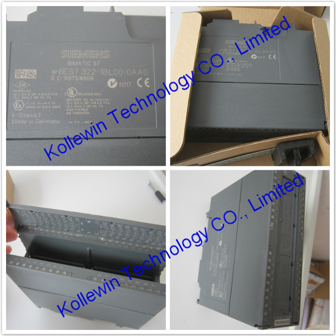


Our company have the compatible product, named 6GK1500-0EA02 ,  can replace Siemens one.

You can have a look on the picture.

6GK1500-0EA02

You can get it only need USD24.00/pc.    Buy now ====>buy buttom
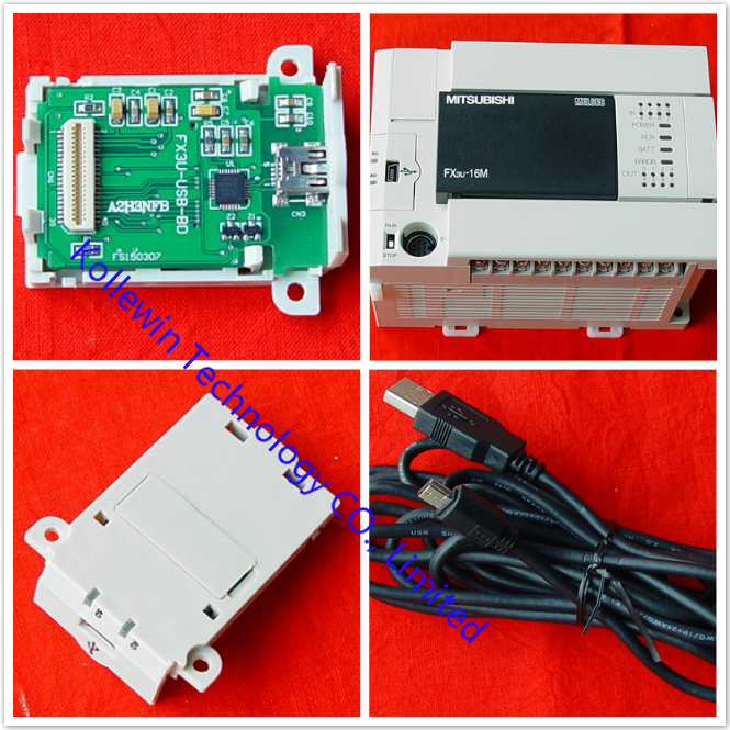
It's tested before shippment.Not made by Siemens,OEM product as the replacement.

The quality is guaranteed, we have 1 year warranty for our compatible products.
More details:

Product
Article Number 6GK1500-0EA02
Product Description PB BUS CONNECTOR
WITH AXIAL CABLE OUTLET
F.INDUSTR. PC, SIMATIC OP, OLM;
TRANSMISSION RATE 12 MBIT/S;
TERMINATING RESISTOR WITH
SEPARATING FUNCTION,
METAL HOUSING
Price p. item*
*Recommended Retail Price
Price On Request
Customer Price Price On Request
Country of origin CN
Export Control Regulations AL: N / ECCN: N
Delivery Time 3-5 Days
Net Weight (kg) 0.049 Kg
Quantity Unit  Piece
Packaging Type Piece
Packaging Quantity 1
Minimum order quantity 1
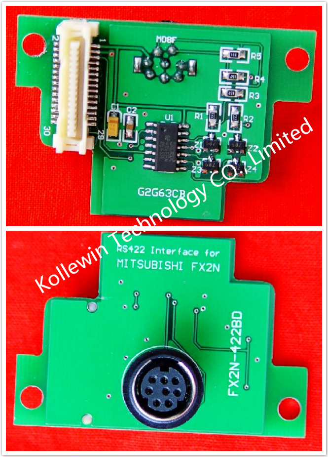
 

Not made by Siemens,but the quality is 100% guaranteed,1 year warranty.
Feel free to contact us for any question.