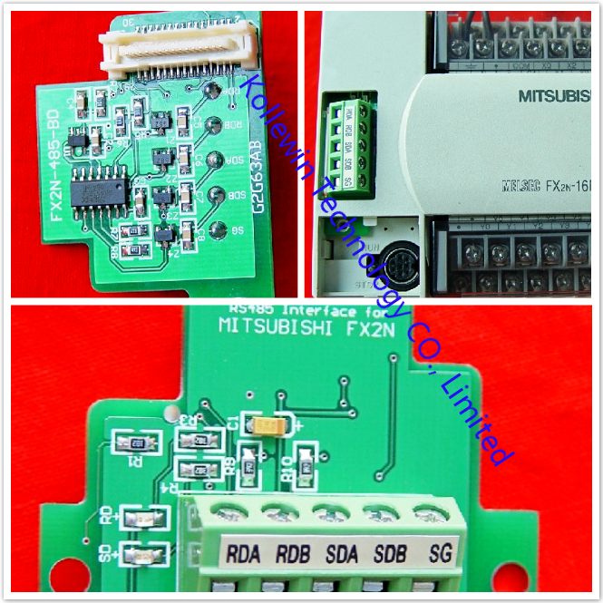
Introduction to Mitsubishi FX2N-485-BD+
The communication board FX2N-485-BD for RS485 (hereinafter referred to as “485BD”) can be connected to the base unit of the FX2N Series programmable controller to be used for the following applications.
1) Data transfer using no protocol
Data communication with diversified RS232C units including personal computers, bar code readers and printers can be performed via the RS485 (422) converter using the no protocol. In this application, data is sent or received using the data registers specified by the RS instruction. For the setting and program examples, refer to the FX Programming Manual and FX Communication User’s Manual.
2) Data transfer using the dedicated protocol
Data transfer with RS485 (422) units can be performed on the 1:N basis using the dedicated protocol.
For the contents of the dedicated protocol used in this application, refer to the FX Communication User’s Manual.
3) Data transfer using the parallel link
Data transfer with an FX2N programmable controller can be performed on the 1:1 basis for 100 auxiliary relays and 10 data registers. For the setting and program examples, refer to the FX Communication User’s Manual.
4) Data transfer using the N:N network
Data transfer with FX2N programmable controllers can be performed on the N:N basis. For the setting,the number of transferred data and program examples, refer to the FX Communication User’s Manual.
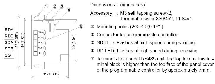
1.1 External Dimensions of Mitsubishi FX2N-485-BD+
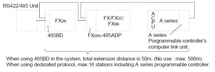
1.2 System Configuration of Mitsubishi FX2N-485-BD+
1.2.1 No Protocol or Dedicated Protocol of Mistubishi FX2N-485-BD+
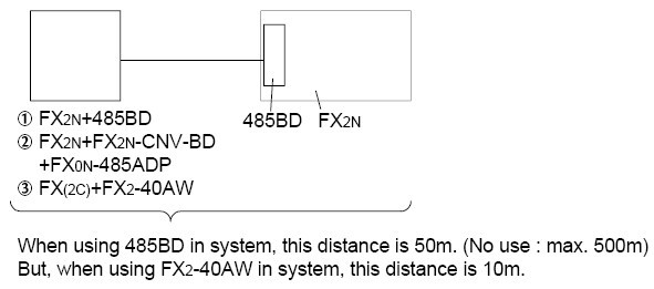
1.2.2 Parallel Link of Mistubishi FX2N-485-BD+
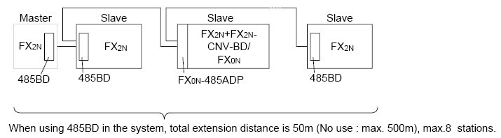
1.2.3 N:N Network of Mistubishi FX2N-485-BD+
MUNTING AND WIRING of Mitsubishi FX2N-485-BD+
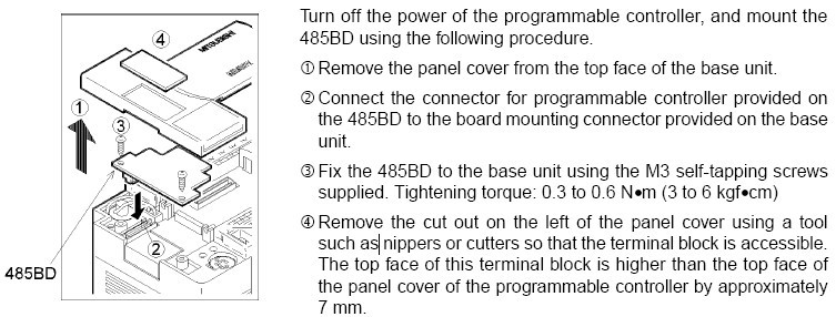
2.1 Mounting Procedure to Mistubishi FX2N-485-BD+
2.2 Cable and Terminal Resistor to connect the RS485 FX2N-485-BD+
2.2.1 Cable to connect Mistubishi FX2N-485-BD+
To connect the RS485 (422) unit, use a shielded twisted-pair cable.
The cable specification must be AWG 26 to 16, and the maximum tightening torque must be 0.6 N·m (6 kgf·cm). If a cable other than the AWG 26 to 16 is used, normal communication cannot be assured because the terminal may be imperfectly contacted. It is recommended to insert a cable integrated by the crimping tool into the terminal.
2.2.2 Terminal Resistor of Mistubishi FX2N-485-BD+
Provide the terminal resistor at both ends of the line as described in section 2.3.2 and 2.3.3.
1) In the case of two-pair wiring, connect the terminal resistor (330W, 1/4W) between terminals SDA and SDB as well as between terminals RDA and RDB.

Use the resistors offered as accessories of the 485BD.
2) In the case of one-pair wiring, connect the terminal resistor (110W, 1/2W)between terminals RDA and RDB. Use the resistors offered as accessories of the 485BD.
2.3 Wiring of Mitsubishi FX2N-485-BD+
2.3.1 Selection of Wiring of Mistubishi FX2N-485-BD+
Wiring of RS485 is one-pair wiring or two-pair wiring. The wiring method is decided according to the
usage. Please select the wiring method from the table below.
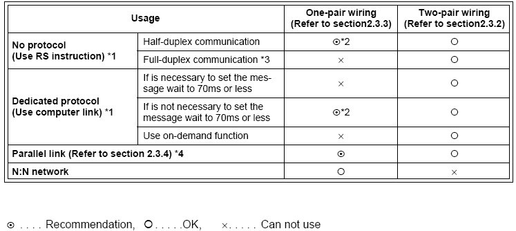
*1 When this product is added to the system, please match the wiring to the wiring method of the system.
*2 When using 485BD with, this wiring method remember to take account of/or ignore the “echo” of the commands sent from the FX2N programmable controller.
*3 Use FX2N programmable controller and 485BD together.
*4 For excluding the combination of 485BD, please see below.
2.3.2 Two-pair Wiring
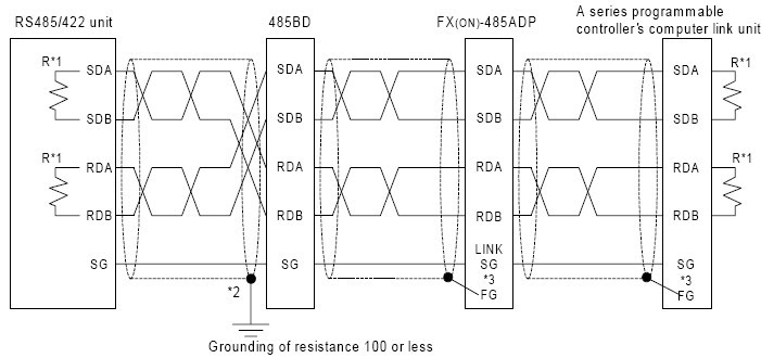
*1 R is the terminating resistance. Connect the terminating resistance (330W) between terminals SDA and SDB, and terminals RDA and RDB.
*2 The shield of the shielded twisted-pair cable must be connected to ground (100W or less). When using parallel link, ground both side. When using no protocol or dedicated protocol, ground one side.
*3 Connect terminal FG to each terminal of the programmable controller main body grounded with resistance of 100 or less. However, for the computer link unit of the A series programmable controller, see the manual of the computer link unit.
*4 When using RS232/485 or RS232/422 interface, please the use FX-485PC-IF.
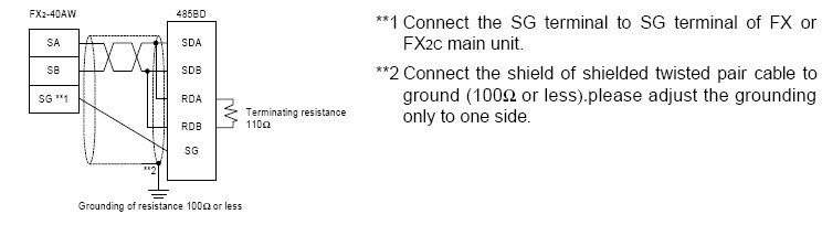
2.3.3 One-pair Wiring
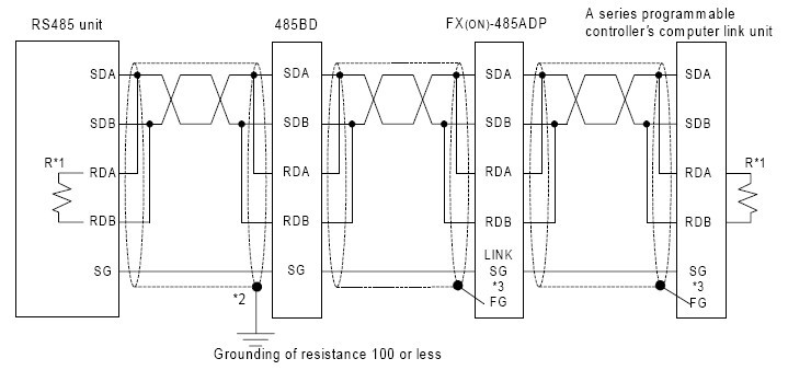
*1 R is the terminating resistance. Connect the terminating resistance (110W) between terminals RDA and RDB.
*2 The shield of the shielded twisted-pair cable must be connected to ground (100W or less). When using parallel link, ground both side. When using no protocol or dedicated protocol, ground one side.
*3 Connect terminal FG to each terminal of the programmable controller main body grounded with resistance of 100 or less. However, for the computer link unit of the A series programmable controller, see the manual of the computer link unit.
*4 When using RS232/485 or RS232/422 interface, please the use FX-485PC-IF.
SPECIFICATIONS of Mitsubishi FX2N-485-BD+
3.1 General Specifications of Mitsubishi FX2N-485-BD+
General specifications are the same as those for the FX2N series programmable controller.
3.2 Power Supply Specification of Mitsubishi FX2N-485-BD+
5V DC, 60 mA is supplied from the programmable controller.
3.3 Specification of Mitsubishi FX2N-485-BD+
|
Item
|
Content
|
|
Transmission standard
|
Conforming to RS485 and RS422
|
|
Transmission distance
|
Max. 50 m
|
|
LED indicators
|
SD, RD
|
|
Item
|
Content
|
Communication
method
and protocol
|
N:N network
|
Half-duplex communication
|
Dedicated protocol
(format 1 or format 4)
|
|
Parallel link
|
|
No protocol
|
Full-duplex communication
|
|
Supported baud rate
|
Dedicated protocol and no protocol: 300 ~ 19,200 (bps)
Parallel link : 19,200 (bps)
N:N network : 38,400 (bps)
|
|
Isolation
|
No isolation
|
DIAGNOSTICS of Mitsubishi FX2N-485-BD+
For error code of N:N network and computer link, refer to the FX Communication User’s Manual.
4.1 Common Items
1) Check the connection with the communication unit of the programmable controller and the wiring.
When the connection is unstable, the communication can not be corrected.
2) Check whether the VRRD or VRSC instruction is used in used in the program.
If it is used, delete it, turn off the power of the programmable controller, then turn it on again.
3) Each setting of communication format (D8120), parameter of programmable controller by FX-PCS/WIN-E, N:N network (D8173 to D8180) and parallel link (M8070, M8071) is suitable for the usage or it checks. The communication is not correctly done if setting is not suitable for the usage.
When each setting is changed, please turn off the power supply of the programmable controller, and turn it on again.
4) When you use FX0N-485ADP or FX-485ADP in network, please the power supply for the drive must be supplied correctly or check.
4.2 LED Check Items of Mitsubishi FX2N-485-BD+
4.2.1 N:N Network
1) Check the status of the RD LED and the SD LED provided on each 485BD.
- If both of them are lit and extinguished, nothing is wrong.
- If the RD LED is lit/extinguished but the SD LED is not lit/extinguished (not lit at all), check the setting of the station No.,the baud rate (transmission rate) and the total number of salve stations.
- If the RD LED is not lit/extinguished, check the wiring.
2) Make sure that the communication error (FX2N: M8183 to M8190, FX0N: M504 to M511) in each slave station is not turned on and that the data communication flag (FX2N: M8191, FX0N: M503) is not turned off. When one of the communication error flag is turned on or if the data communication flag is turned off, check the error code of data registers (FX2N: D8211 to D8218, FX0N: D211 to D218).
For the error code, please see the FX Communication User’s Manual.
4.3 Parallel Link
1) Check the status of the RD(RXD) LED and the SD(TXD) LED provided on each communication unit.
- If both of them are lit and extinguished, nothing is wrong.
- If the RD(RXD) LED is lit/extinguished but the SD(TXD) LED is not lit/extinguished (not lit at all),check the setting of the master station and the slave stations.
- If the RD(RXD) LED is not lit/extinguished, check the wiring.
2) Make sure that the master station and the slave stations are set correctly. If the setting is incorrect,correct it.
3) Make sure that the devices for the master station and the slave stations are handled correctly. If they are handled incorrectly, correct the program so that they are handled correctly.
4.4 Computer Link
1) Check the status of the RD(RXD) LED and the SD(TXD) LED provided on each communication unit.
- If both of them are lit and extinguished, nothing is wrong.
- If the RD(RXD) LED is lit/extinguished but the SD(TXD) LED is not lit/extinguished (not lit at all),check the setting of the station No. and the transmission rate (baud rate).
- If the RD(RXD) LED is not lit/extinguished, check the wiring and confirm the connection with the programmable controller.
2) Make sure that the communication procedure is performed correctly. If it is not performed correctly,correct the setting in the computer.
3) Check the NAK error code and programmable controller error code.
For the error code, please see the FX Communication User’s Manual.
4.5 RS Instruction
1) Check the status of the RD (RXD) LED and the SD (TXD) LED provided in an optional equipment.
- If the RD (RXD) LED is not lit while data is received or the SD (TXD) LED is not lit while data is sent, check the installation and the wiring.
- When the RD (RXD) LED is lit while data is received or the SD (TXD) LED is lit while data is sent, the installation and the wiring are correct.
2) Make sure the timing of data send/receive. For example, make sure that the counterpart equipment is ready for receive before starting to send data to it.
3) When the terminator is not used, check whether the send data capacity is equivalent to the acceptable data capacity. If the send data capacity may be changed, use the terminator.
4) Make sure that the external equipment is correctly operating.
5) Check whether the type of send data and the type of receive data are equivalent. If they are different,make them equivalent.
6) When two or more RS instructions are used in the program, make sure that only one RS instruction is actuated in one operation cycle. Never turn off the RS instruction while data is received or sent.
7) In the FX2N Series (V2.00 or later), an RS instruction is not executed if the counterpart equipment receives “NAK”.
Arrange the system so that the RS instruction is executed even if the counterpart equipment receives “NAK”.
Our company (Kollewin Technology CO., Limited) have new products.
Named FX2N-485-BD+ .
They are 100% compatible with Mitsubishi original FX2N-485-BD.
Part#:FX2N-485-BD+
The unit price is USD62.89/pc 
USER'S MUNUAL PDF of communication board FX2N-485-BD
FX2N-485-BD-USER'S MANUAL

Specification of communication board FX2N-485-BD+:
|
Product Name
|
Communication Board
|
|
Fit
|
for Mitsubishi FX2N PLC
|
|
Model NO.
|
FX2N-485-BD
|
|
Interface
|
Conforming to RS485 and RS422
|
|
Connector Type
|
Mini Din 8 Pin
|
|
Voltage
|
DC 5V
|
|
Current
|
60mA
|
|
Max.Transmission Distance
|
50M
|
|
LED Indicators
|
SD, RD
|
|
Communication Method
|
Half-duplex
|
|
Insulation
|
No Insulated
|
|
Material
|
Plastic, Metal
|
Description of communication board FX2N-485-BD+:
-
FX2N are suitable for use with FX2N PLC's. FX2N-232-BD are used for RS-485 applications, such as communication with a PC, printer or bar code reader. and provide a second programming port which enables an operator panel (or HMI) and a programming panel to be connected to the PLC at the same time.
-
This is a Replacement of Mitsubishi FX2N-485-BD Programmable Controller.
-
This is OEM product, not Mitsubishi original part.
More communication boards we have
FX2N-485-BD+
FX2N-485-BD
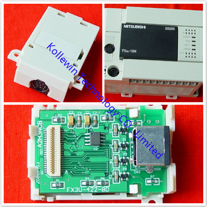
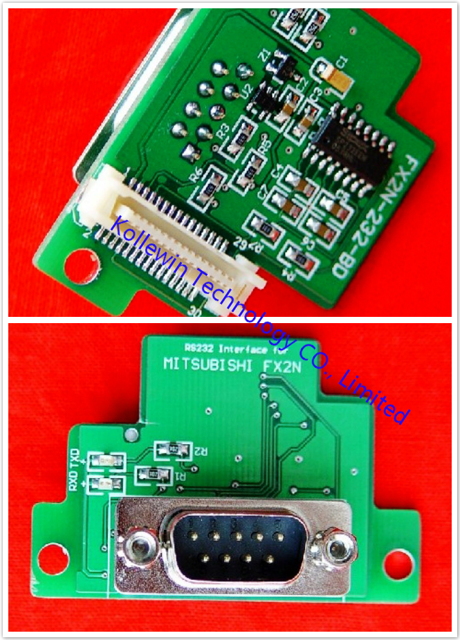
FX2N-422-BD
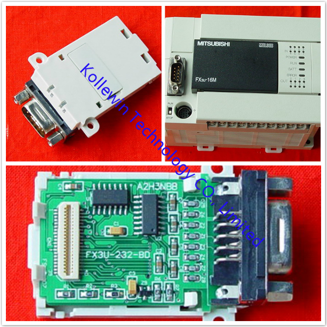
FX2N-232-BD
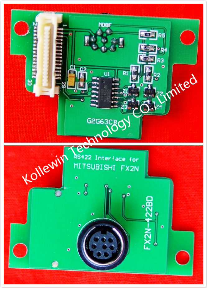
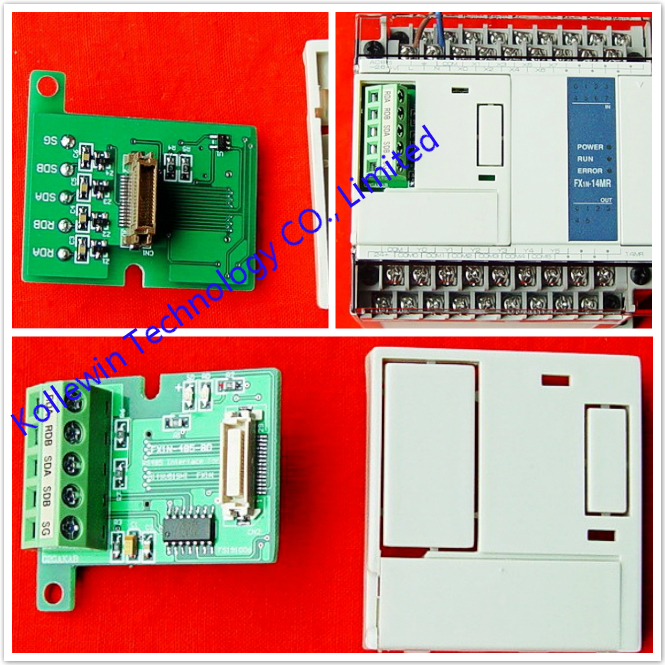
FX1N-485-BD
FX1N-422-BD
FX3U-485-BD
FX3U-422-BD
FX3U-232-BD
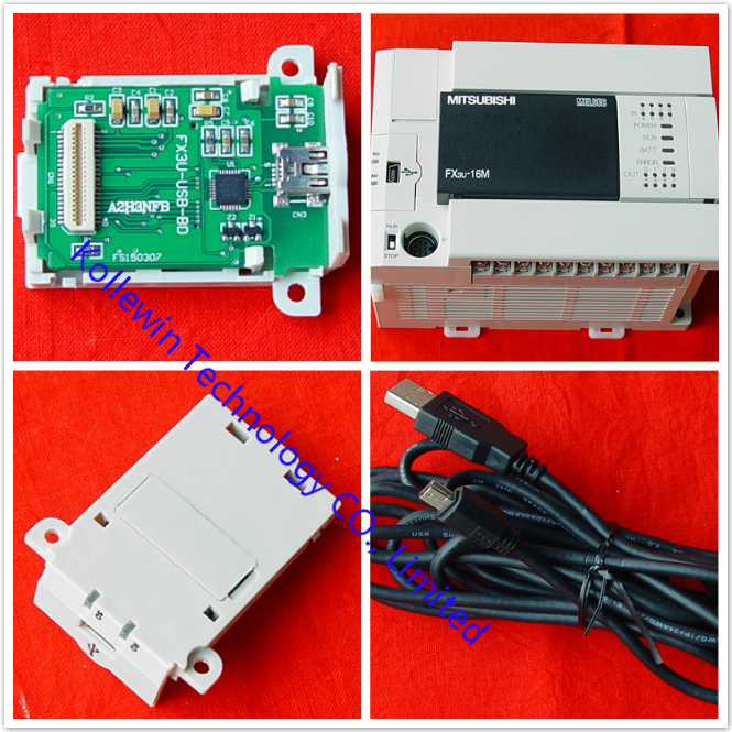
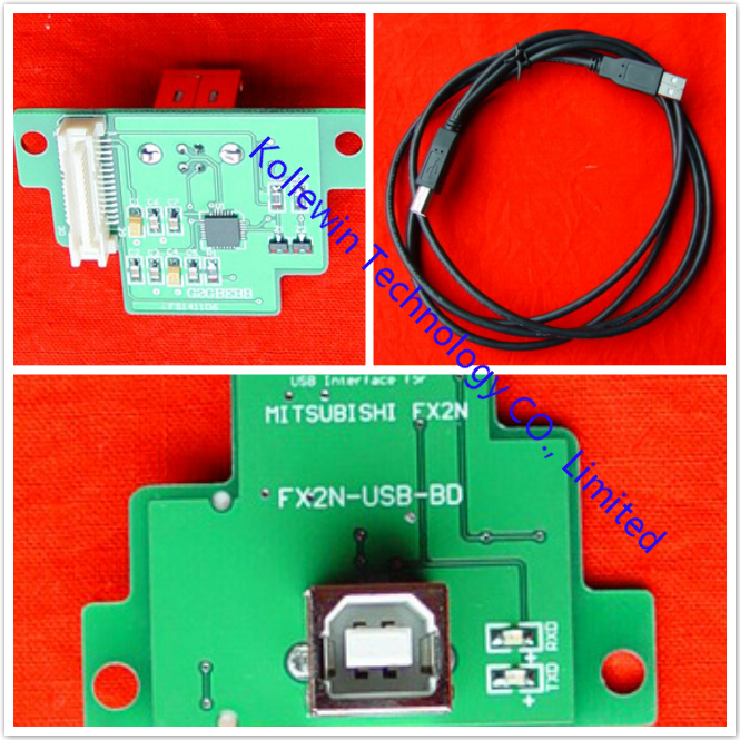
FX3U-USB-BD
FX2N-4DA
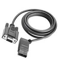
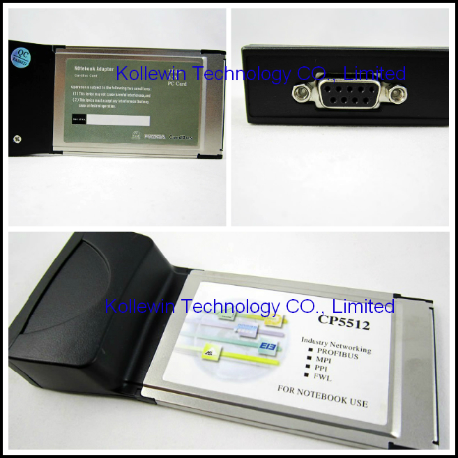
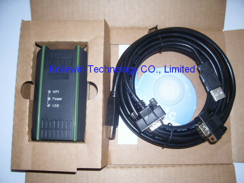
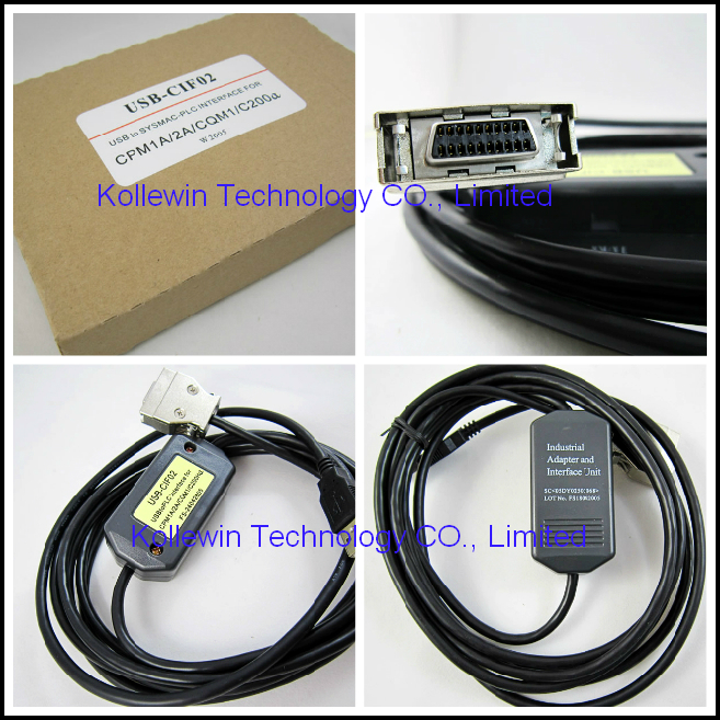
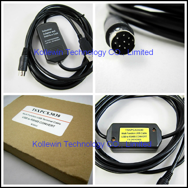
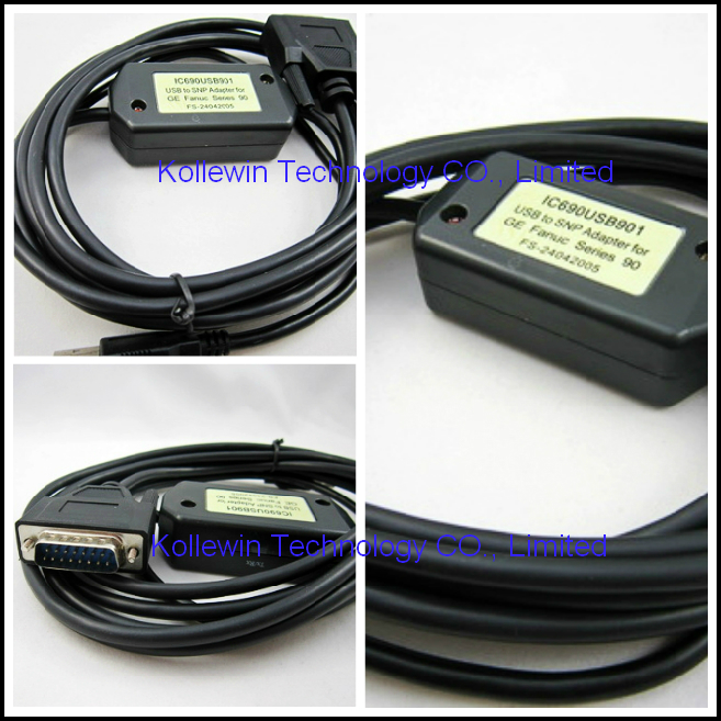
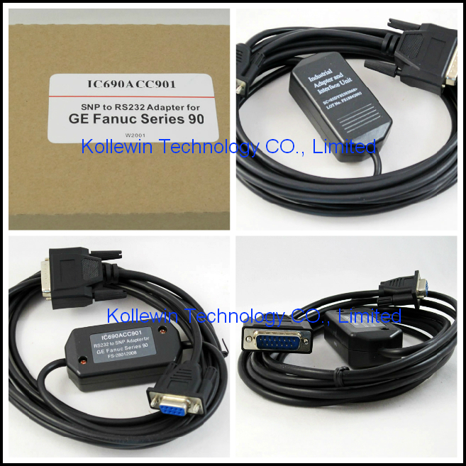
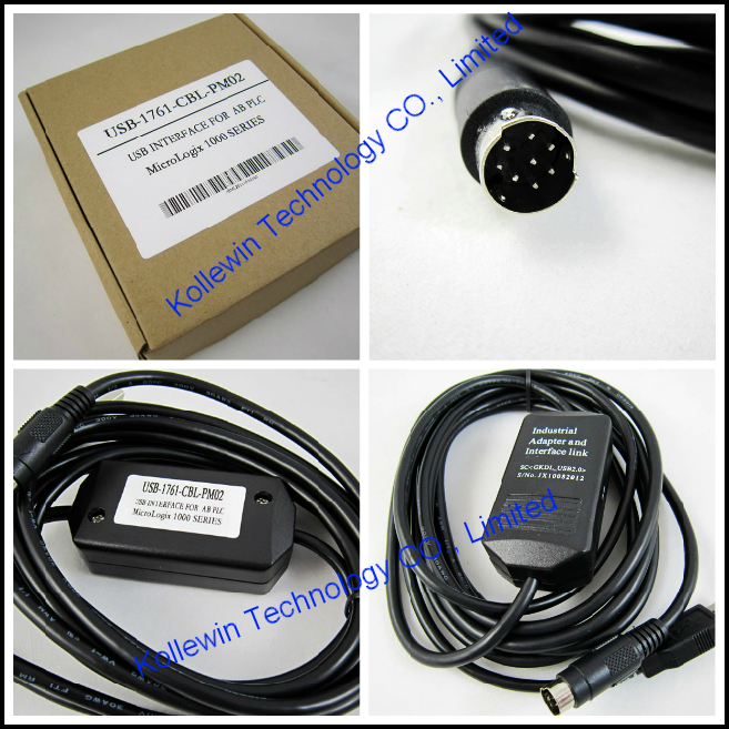
More pictures of PLC communication board


Please feel free to contact me for any question!
Contact person: Miss Nancy


Recent Comments